.jpg)


Guide to Installing Low Voltage Dry-Type Transformers
Learn how to install a low voltage dry-type transformer with this general guide covering wiring, primary tap settings, grounding, anchoring, and NEC compliance.
How To's
Installing a transformer correctly is critical to safe and reliable operation.
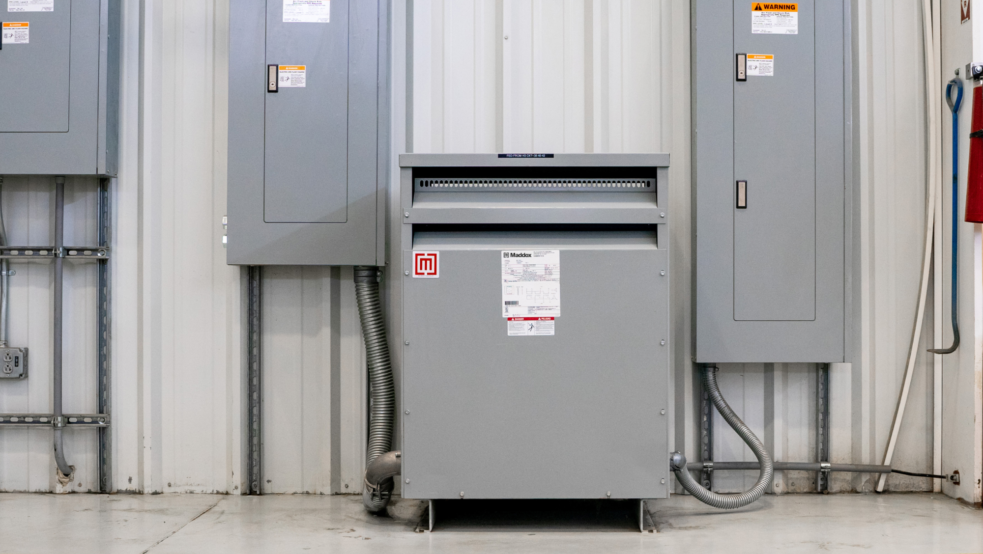
In this article, we’ll walk through the step-by-step process for installing a three-phase, general-purpose dry-type transformer.
Installation Warning
This article is a general guide. Always be sure to follow the established rules and documentation for your specific transformer including the installation manual, the nameplate, and all applicable electric codes and laws. This guide focuses on the physical installation process of just the transformer and assumes correct disconnection means and overcurrent protection already installed in the building.
Transformer installation and removal should only be performed by a qualified electrical professional.
Continue reading or check out our video below.
Dry-Type Transformer Installation Process
1. Safety Checks
There are three things you should do before you start any work:
Get your PPE
Always make sure you’re wearing personal protective equipment (gloves, eye protection, arc-rated clothing, etc.)
Verify the voltage
Measure and record the voltage on the service side feeding the transformer. You’ll reference this measurement later when setting primary taps.
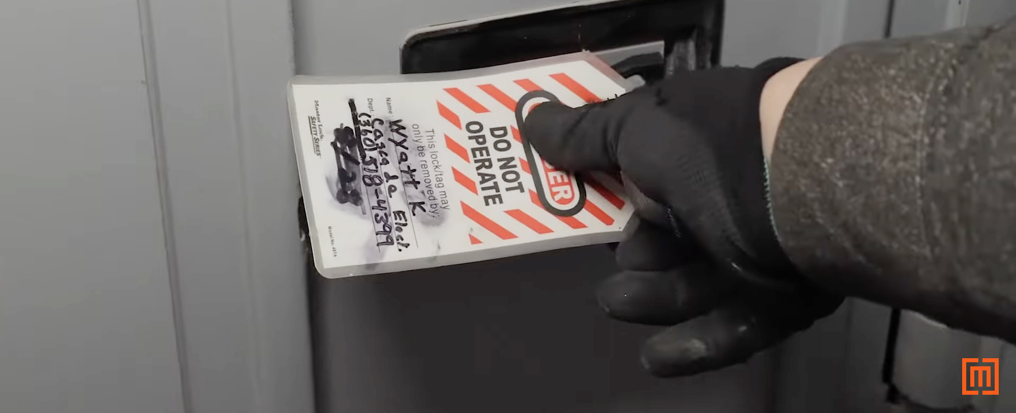
De-energize and lock out
De-energize the circuit feeding the old transformer that will be replaced (if applicable). Apply lockout/tagout procedures and verify zero voltage before proceeding.
2. Gather Required Tools
Here are the tools you typically need for a dry-type transformer installation:
- Lockout/tagout equipment
- Socket set
- Torque wrench
- Drill
- Concrete anchors
- Hole punch or knockout set
- Grounding lugs and conductors
- Razor knife or wire brush
- Level
- Tape measure
3. Remove the Existing Transformer (If Applicable)
If you are replacing an existing transformer, follow the steps below. If you are installing a transformer in a place that didn’t have one skip to step 4.
- Turn off and lock out the breaker feeding the old transformer.
- Remove the transformer’s front panel.
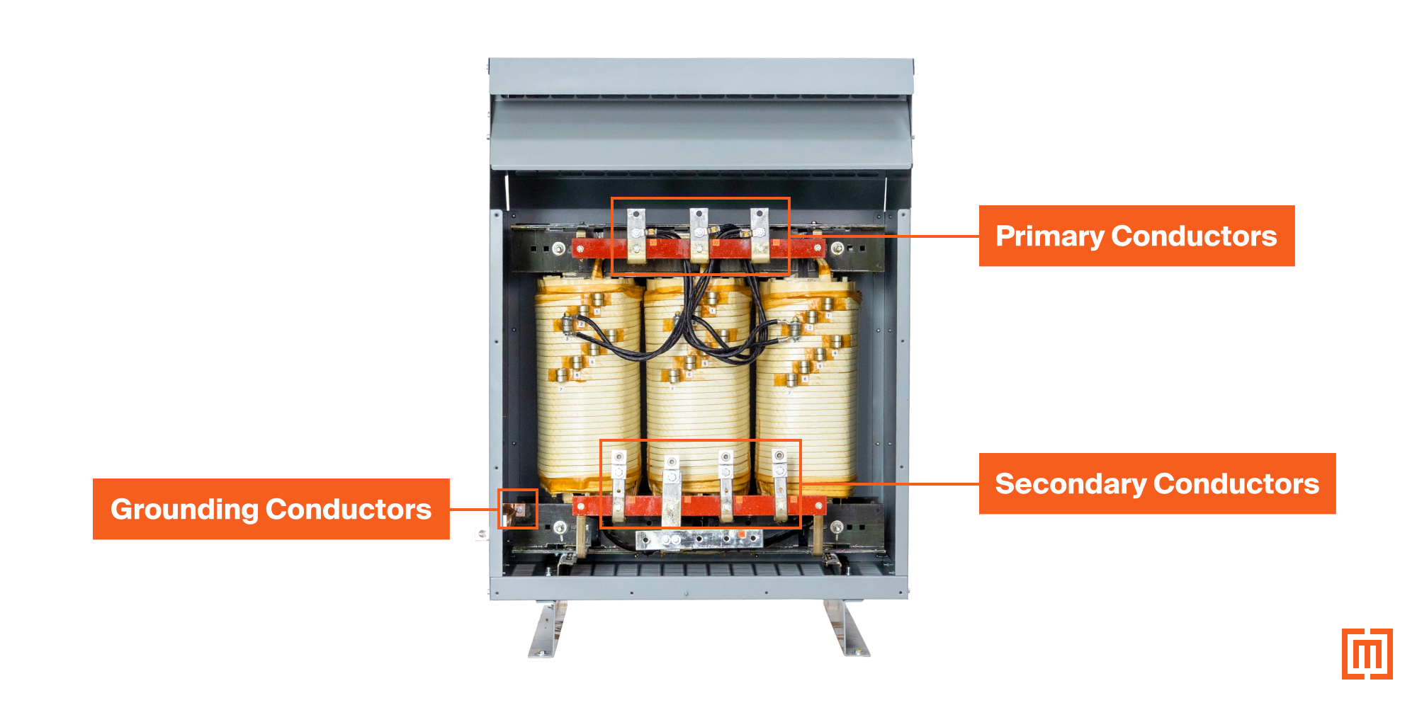
- Disconnect all wiring in this sequence:
- Primary conductors first from the primary terminals
- then secondary conductors from the secondary terminals
- Finally, all grounding and bonding conductors
- Unbolt the transformer from the floor anchors.
- Remove the transformer from the installation area.
4. Inspect the new transformer.
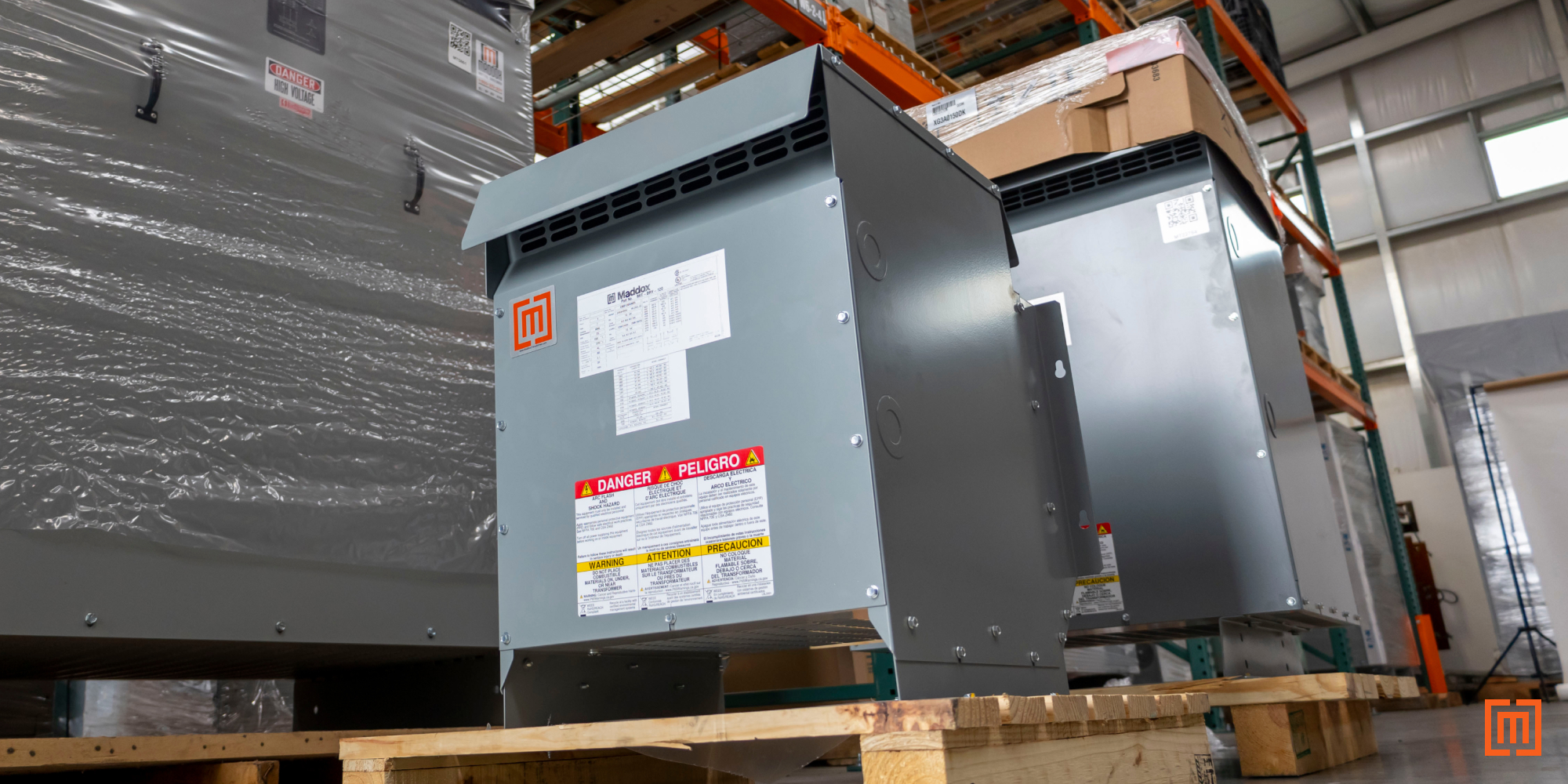
Once the old unit is removed (or if this is a new install), unbox the new transformer and remove it from the pallet.
Review Nameplate Information
- Review all nameplate information carefully to ensure it meets your system’s specs:
- kVA rating
- Primary and secondary voltages
- Phase and frequency
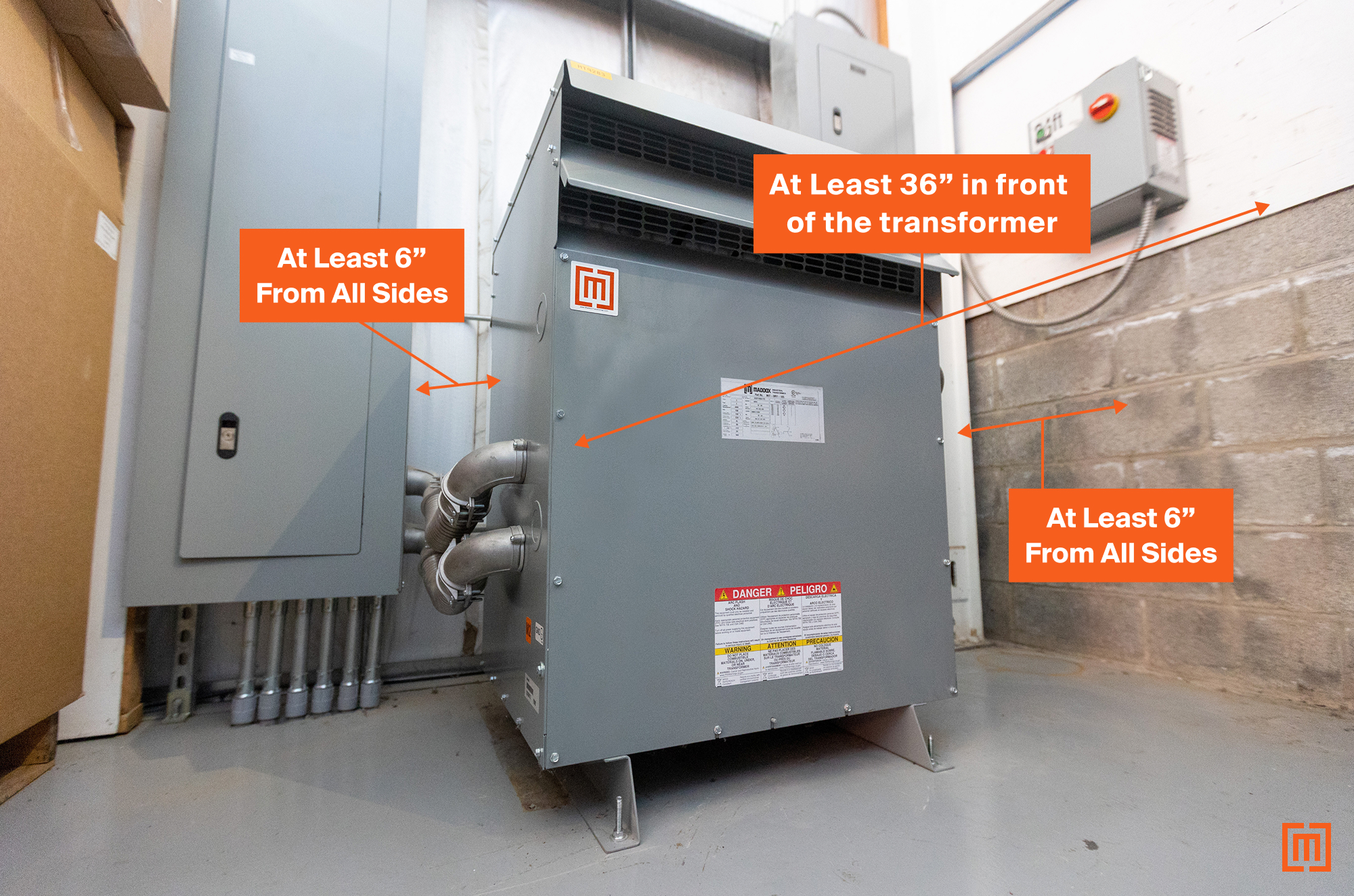
Before moving the new transformer into place, review the ventilation clearance requirements to ensure the location meets the clearance and airflow requirements on all sides. NEC Article 450 typically requires:
- Minimum 6 inches clearance from all sides
- At least 36 inches in front of the transformer
Verify airflow clearance on all sides and confirm the locations of primary and secondary terminals. Some transformers will have them on the front and the back side of the unit.
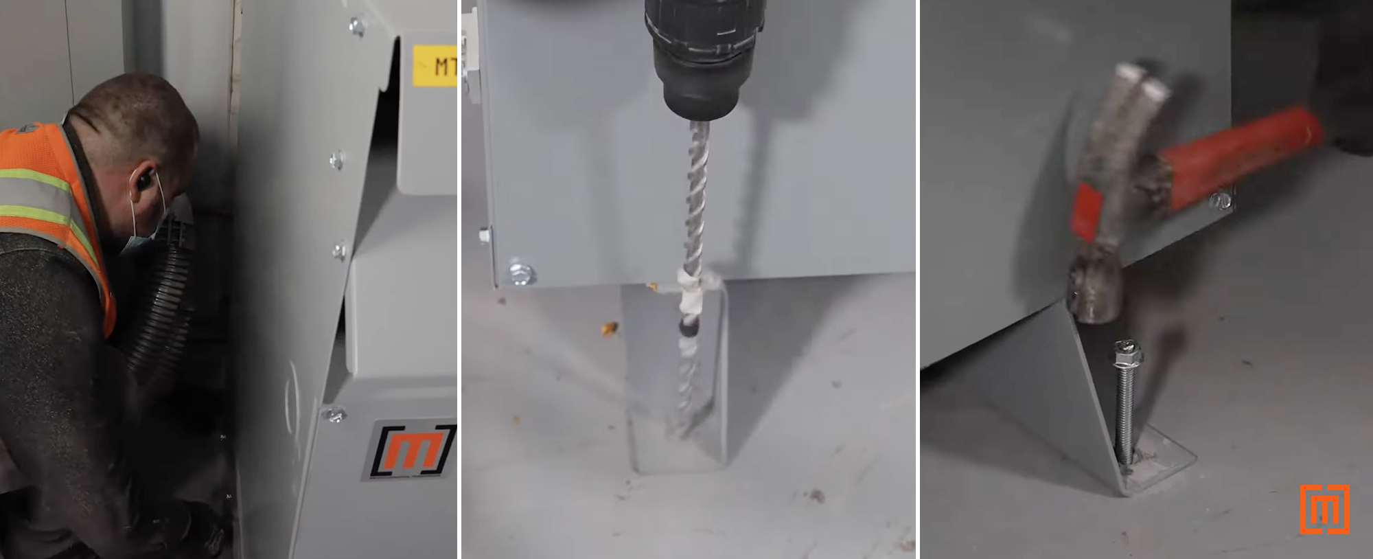
5. Position and Anchor the Transformer
Next, move the transformer into its final location.
- Confirm the transformer is level.
- At this point, you could add vibration pads to reduce the overall transformer noise.
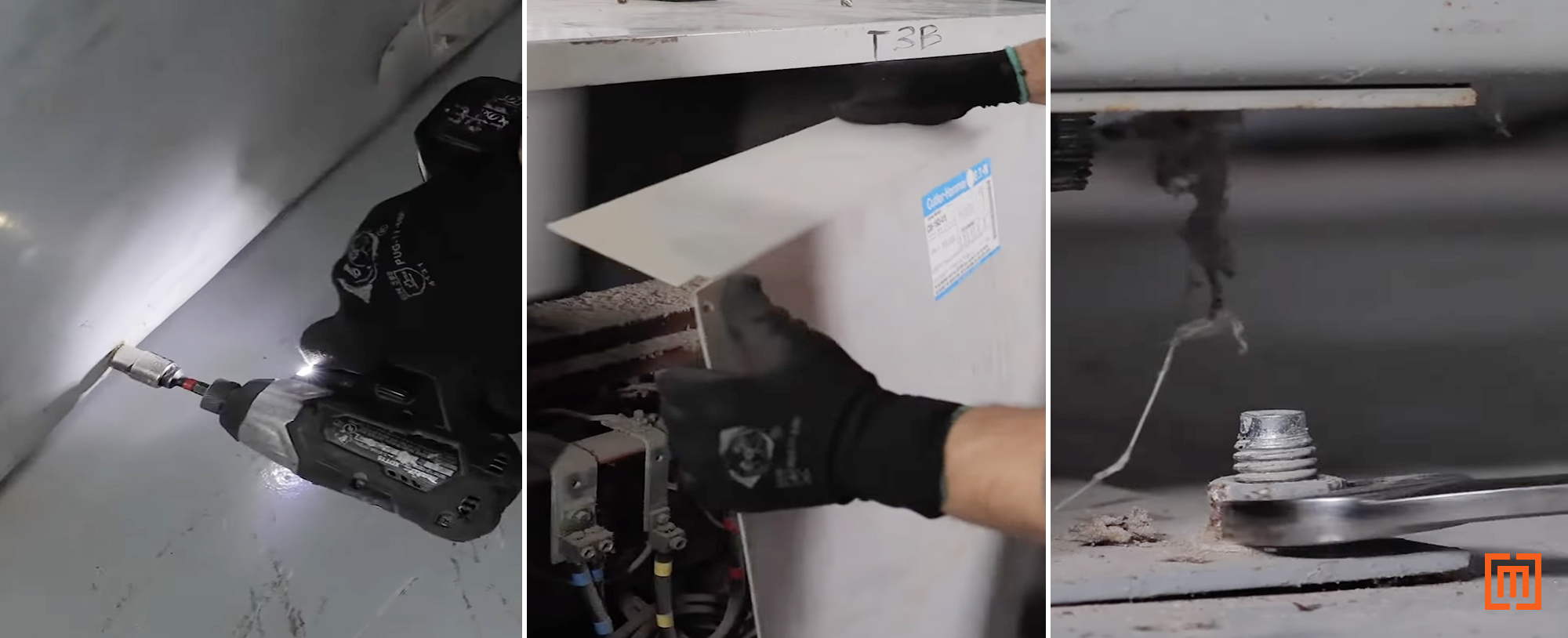
- Use concrete anchors to secure the unit to the floor.
- If present, remove any old anchors.
- Drill holes for new anchors as needed.
- Secure the new transformer firmly to the floor.
6. Adjust the voltage taps.
Next, review the voltage taps.
- Remove the front panel of the enclosure
- Review the tap diagram on the nameplate.
- Confirm whether the taps match the measured primary voltage (from step 1).
Usually, the transformer will be on the nominal tap. (This is usually the third tap from the top in most units.) The tap settings should match the nominal nameplate voltage.
- If adjustments are needed:
- Ensure the transformer is de-energized.
- Remove varnish from tap terminals using a razor knife or wire brush.
- Move each jumper lead to the correct tap position for your system voltage.
- Ensure clean, solid electrical contact on each connection.
- Tighten connections per manufacturer specifications.
Remember, never change tap settings while the transformer is energized.

Also, you may want to slightly loosen the internal isolation pads. This will help reduce the overall transformer’s noise once energized.
7. Make the Knockout Holes
Next punch conduit holes into the transformer enclosure.
- If available, use the factory knockouts.
- Or, create holes manually using a hole punch.
- Feed cables into the transformer enclosure.
- Attach flex conduit to the sides of your transformer enclosure

8. Connect Primary and Secondary Conductors
With conductors routed into the enclosure:
- Verify conductor sizing and phase configuration match the nameplate.
- Secure the conductors to the transformer terminals using mechanical compression lugs.
- Make sure you connect the conductors in the correct sequence.
- Connect primary conductors to the primary lugs
- Connect secondary conductors to the secondary lugs

Be sure to keep wiring clear of ventilation openings to maintain proper airflow.
Also, make sure all conductors are terminated using properly-sized mechanical lugs.
Apply Noalox© (or similar anti-oxidative and corrosion-resistant compound) where needed, and tighten all connections to manufacturer torque specifications.

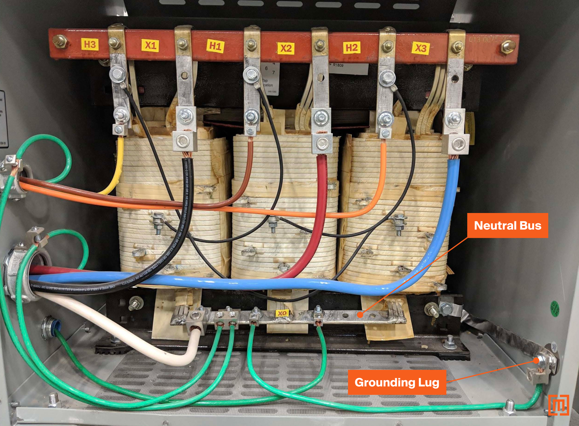
9. Grounding and Bonding
Depending on your code requirements and system set up, follow the steps below. NEC 250.30 requires separately derived systems to be solidly grounded. This means that you almost always ground the neutral (X0) on the output winding of a transformer.
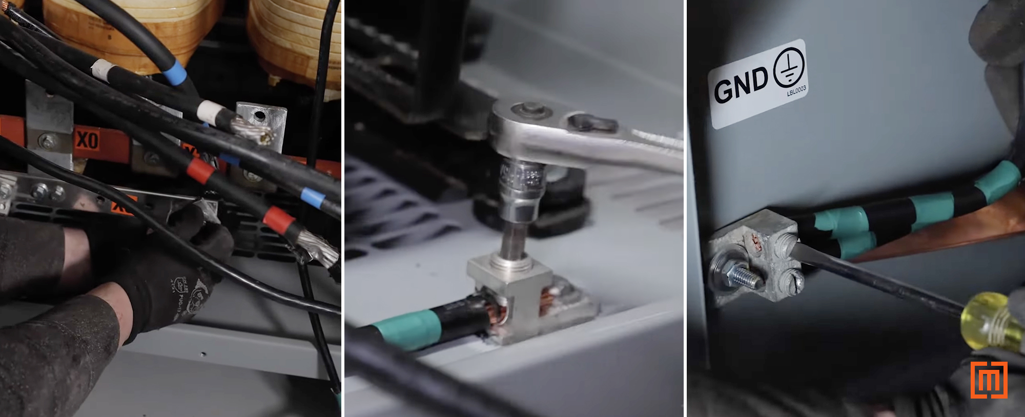
If there is a neutral terminal present inside the transformer, install grounding lugs and bond it to the neutral bus. In the video example, an additional ground lug is added to accommodate a larger-sized bonding jumper:
- Remove paint from the enclosure where grounding lugs are installed to ensure solid metal-to-metal contact.
- Create an opening in the transformer to route grounding electrode conductors.
- Connect grounding electrode conductors to the neutral bus.
- Terminate all equipment grounding conductors.
10. Final Assembly and Testing
Lastly, put everything back together.
- Confirm all of the connections are tight.
- Confirm the grounding is complete.
- Confirm the clearances are maintained.
Lastly, remove the lockout (or tagout) devices. Energize the transformer.
Once the transformer is running, listen for any abnormal noise, and verify proper voltage on the secondary side. If the voltages are not within tolerance, deenergize the unit and adjust primary taps accordingly.
Finally, reinstall the front panel.
Conclusion
Installing a dry-type transformer isn’t necessarily complicated, but it does require care and attention to detail. Proper clearances, solid grounding, correct tap settings, and secure terminations all play a part in keeping the transformer reliable and safe.
Maddox has thousands of low voltage dry-type transformers in stock ready to ship to you. You’ll find these units on our webstore, and they deliver in 3-5 business days. Fill out the form below to get the right transformer for your project.


