


Guide to Radial and Loop Feed Transformers
A loop feed transformer can handle both radial and loop distribution systems, while a radial feed transformer is almost always used in a radial setup.
How To's
For transformers, “loop feed” and “radial feed” usually refer to the high-voltage (HV) bushing layout on padmount transformers. But the terms actually come from broader electrical distribution concepts. A transformer is called “loop feed” because its bushings are designed for a loop distribution system. Likewise, “radial feed” transformers have bushing layouts suited for radial systems.
Between the two, the loop feed design is more versatile. It can fit either system type, while radial feed units typically appear only in radial circuits.
To understand why, let’s look at:
- The basics of radial and loop distribution systems, and
- How those systems affect padmount transformer bushing configurations.
Some jobs allow flexibility in transformer setup. Others require a specific layout.
Radial and Loop Feed Distribution Systems
Both systems have the same goal: deliver medium-voltage power from a source—usually a substation—to one or more step-down transformers serving a load.
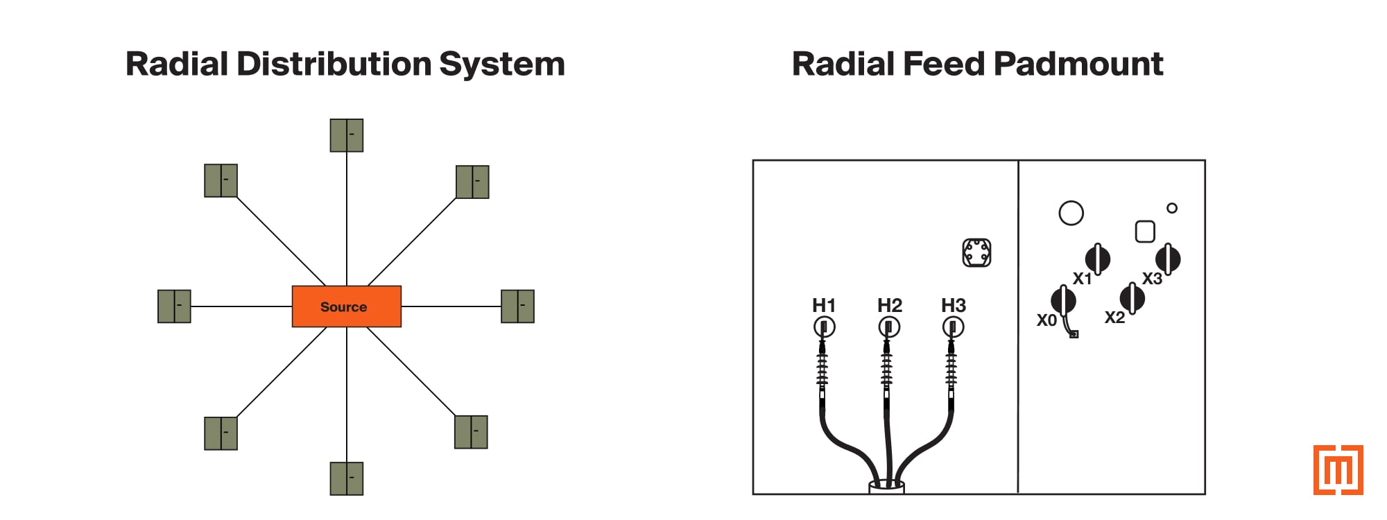
Radial Feed
Radial feed is the simpler of the two. Picture a circle with several lines radiating from the center. The center point is the power source, and the squares at the end of each line are transformers.
Each transformer gets its power from that single point. If a fault or maintenance event takes the source offline, the whole system goes down until it’s fixed.
Loop Feed
In a loop system, transformers can be fed from two or more sources. Instead of one central feed point (like a radial system), power can come from separate locations.
If one power source fails on one side, power can continue flowing from the other source. This redundancy keeps service online—one reason loop systems are common at hospitals, airports, campuses, and large industrial sites.
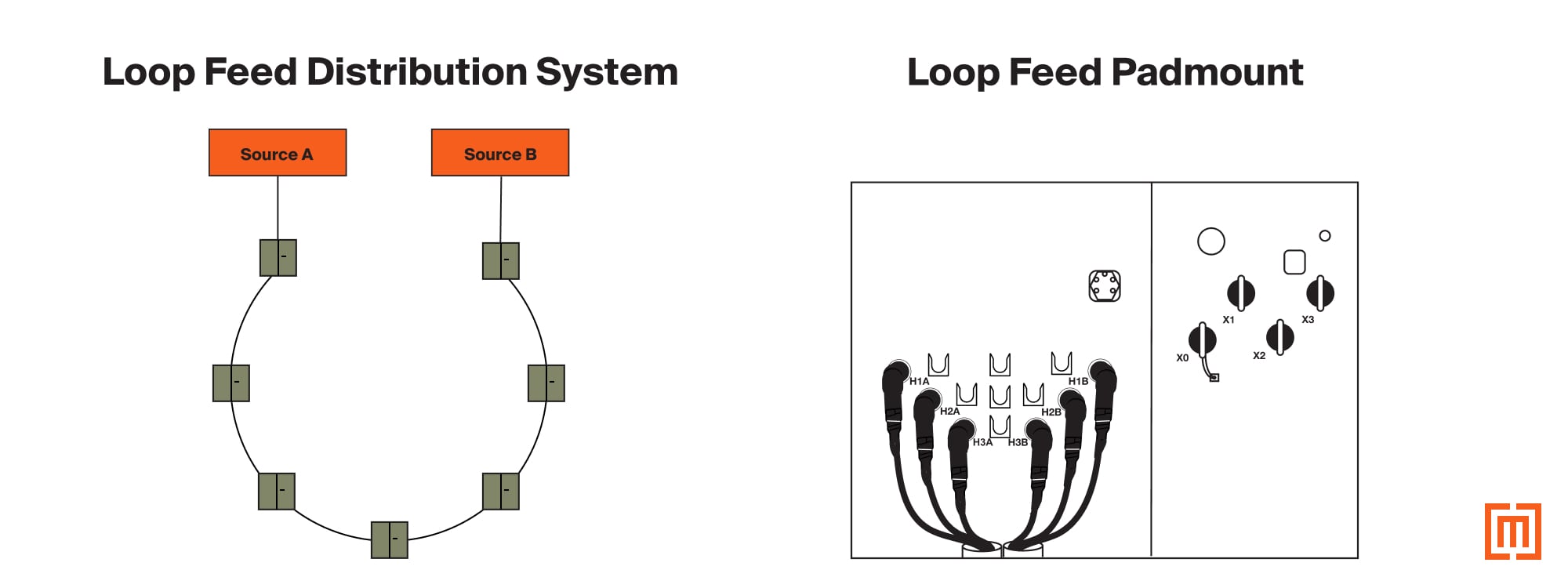
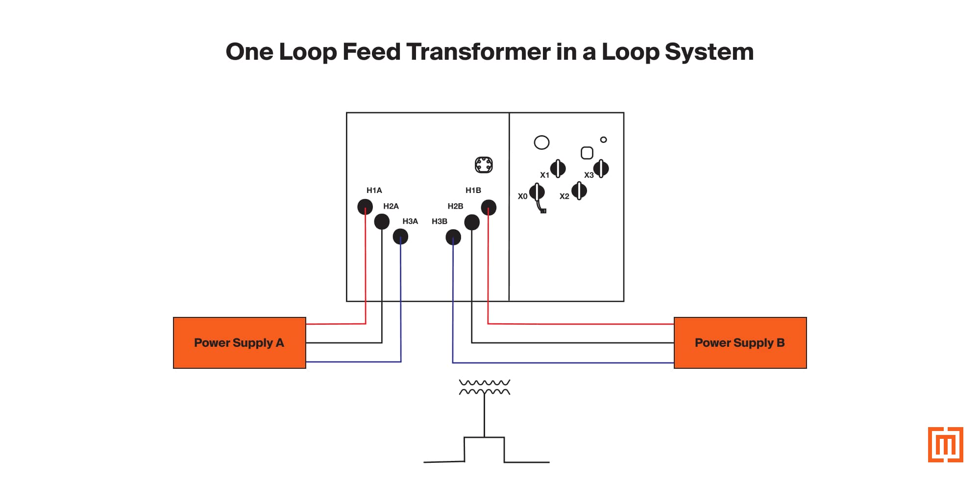
In a loop system, transformers can be fed from multiple sources. If a feeder cable fails near Source A, the system can still run from Source B.
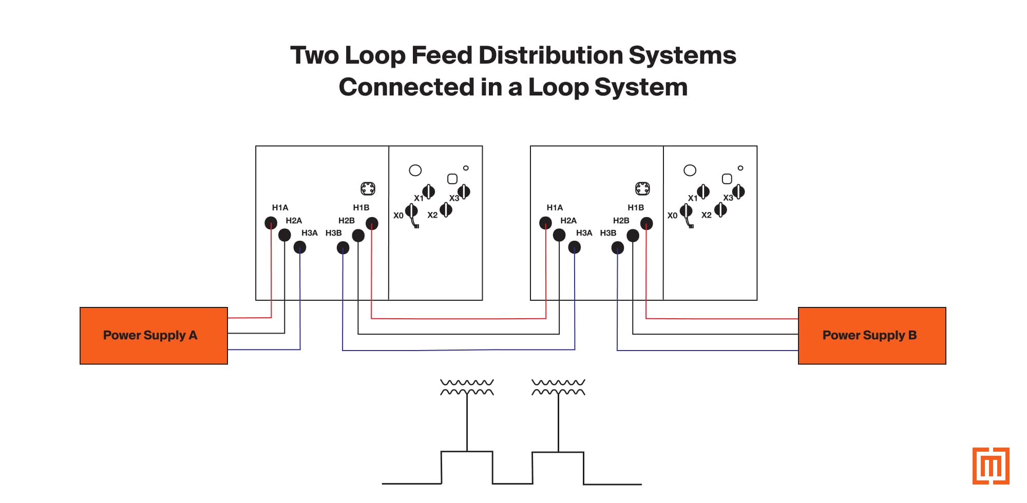
Close-up view of two loop feed transformers connected in a loop system, each capable of being fed from one of two power supplies.
Summary: Radial vs. Loop
If a transformer gets power from only one point in a circuit, it’s in a “radial” system. If it can receive power from two or more points, it’s in a “loop” system.
You can’t always tell which type you’re dealing with just by looking at the transformers. A single-line diagram is the best way to confirm. Still, the primary bushing configuration often gives useful clues.
Radial and Loop Feed Bushing Configurations
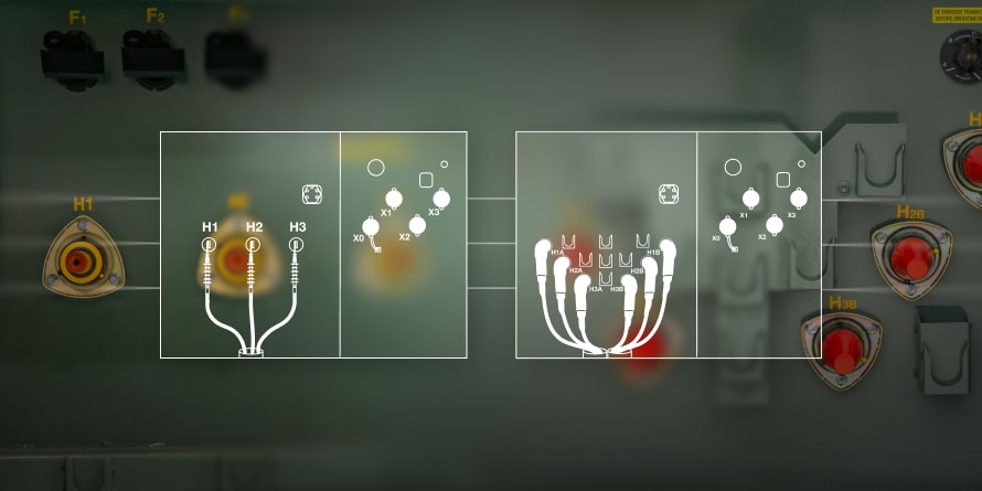
In padmount transformers, the difference between radial and loop feed comes down to the high-voltage (HV) bushing layout.
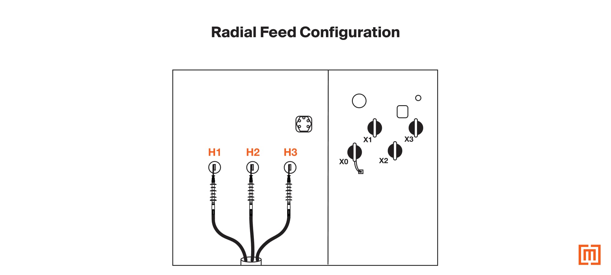
Radial Feed Layout
A radial feed transformer has three primary bushings—one for each incoming phase conductor . This layout is typical when one transformer powers a site or facility. It’s also common for the last transformer in a string of loop feed units.
Loop Feed Layout
Loop feed primaries have six bushings instead of three—two sets of three. The usual setup is a “V loop,” with bushings labeled H1A–H3A on one side and H1B–H3B on the other, per IEEE Std C57.12.34.
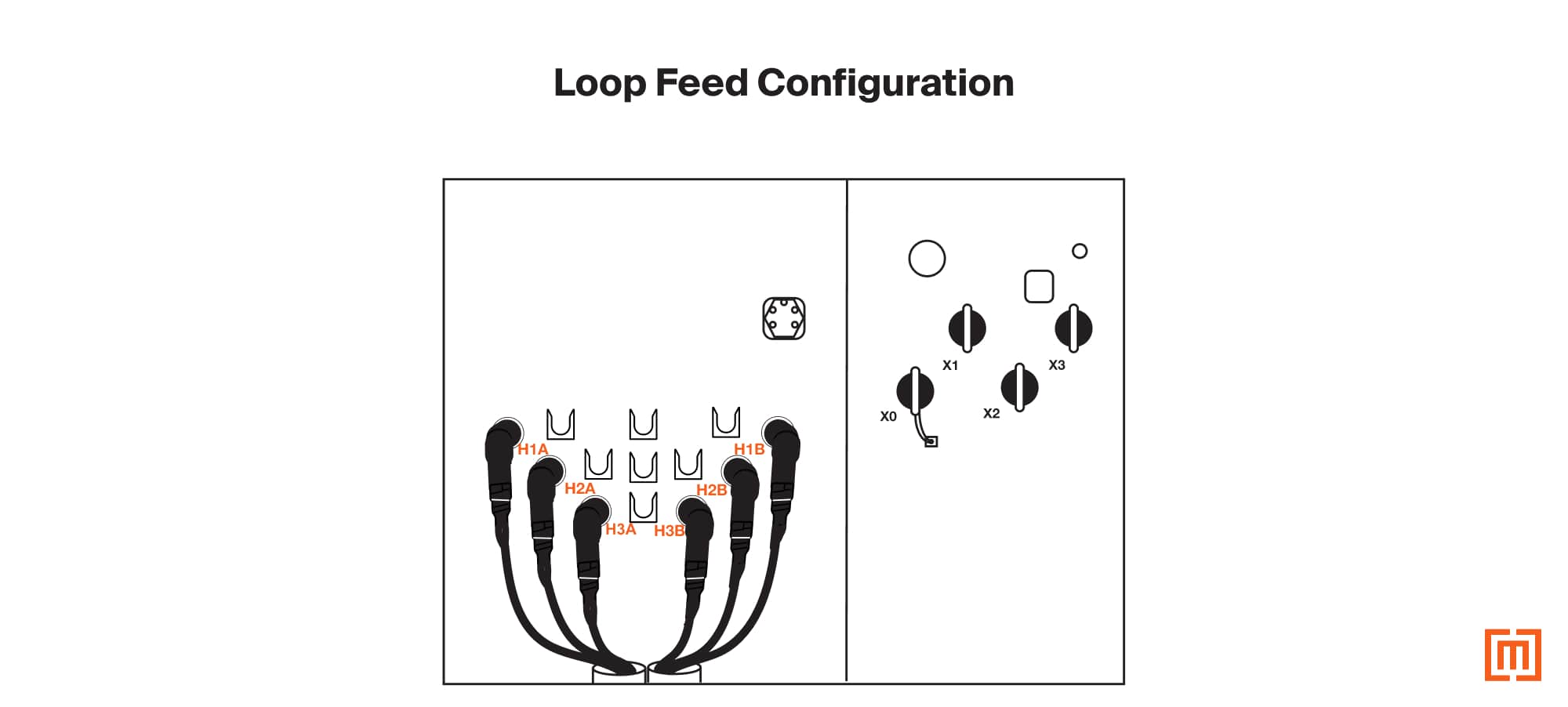
This setup lets you link multiple transformers together. The incoming utility feed enters the first transformer, then passes through to the next via cables connecting the B-side of one unit to the A-side of the next.
This method of daisy-chaining two or more transformers in a row is also referred to as a “loop” of transformers (or “looping transformers together”).
Just note: a “loop of transformers” isn’t the same as a “loop system.” You could have a string of transformers looped together but powered from one source. If that power source goes down, all units go offline—so the system is still radial.
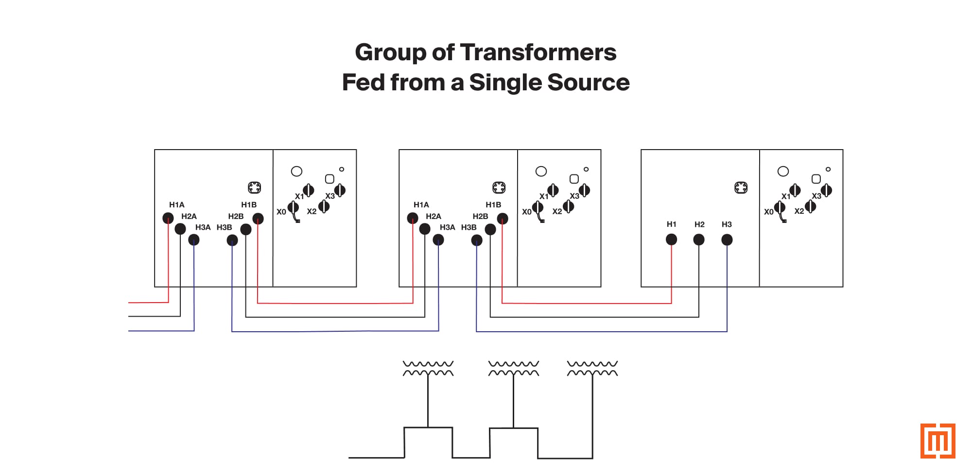
This lineup of transformers shares a single power source. Power passes through each transformer to the final unit, where it’s terminated.
Bayonet Fuse Protection
Internal bayonet fuses on the primary side add a layer of protection . Each transformer can be fused individually, which is especially helpful when multiple units are connected together.
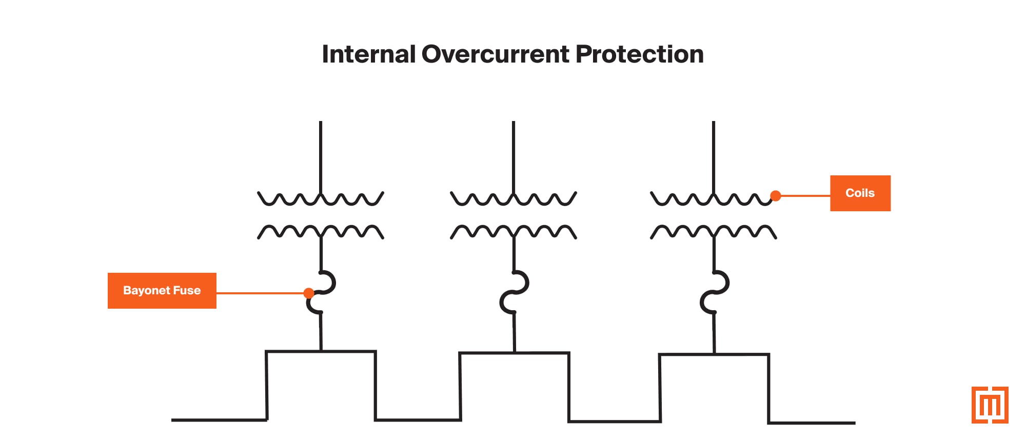
Each transformer has its own internal overcurrent protection.
If a secondary-side fault occurs, the primary fuse isolates that transformer before the fault can spread. The normal current will continue to flow past the faulted unit to the remaining transformers in the circuit. The rest of the system stays online, limiting downtime and damage. This setup with internal overcurrent protection may be used in radial or loop systems–in either case, the expulsion fuse will isolate the faulted unit and the load it serves.
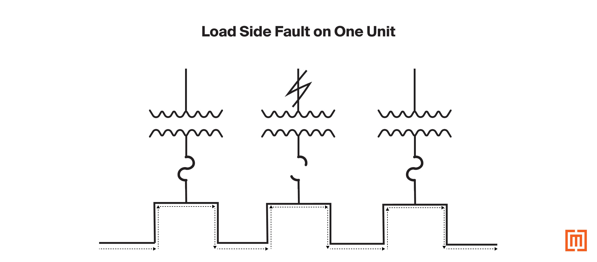
A faulted transformer is isolated by its primary fuse, allowing the others to keep operating.
Two-Source Feed Option
A loop feed configuration also allows a transformer to be fed by two separate sources—Feed A and Feed B. Inside the unit, oil-immersed loadbreak switches allow selecting between feeds as needed. Certain configurations will allow switching between each source feed with no momentary loss of power to the load being served. This is a crucial advantage for end users who value electrical service continuity.
Loop-Feed in Radial Systems
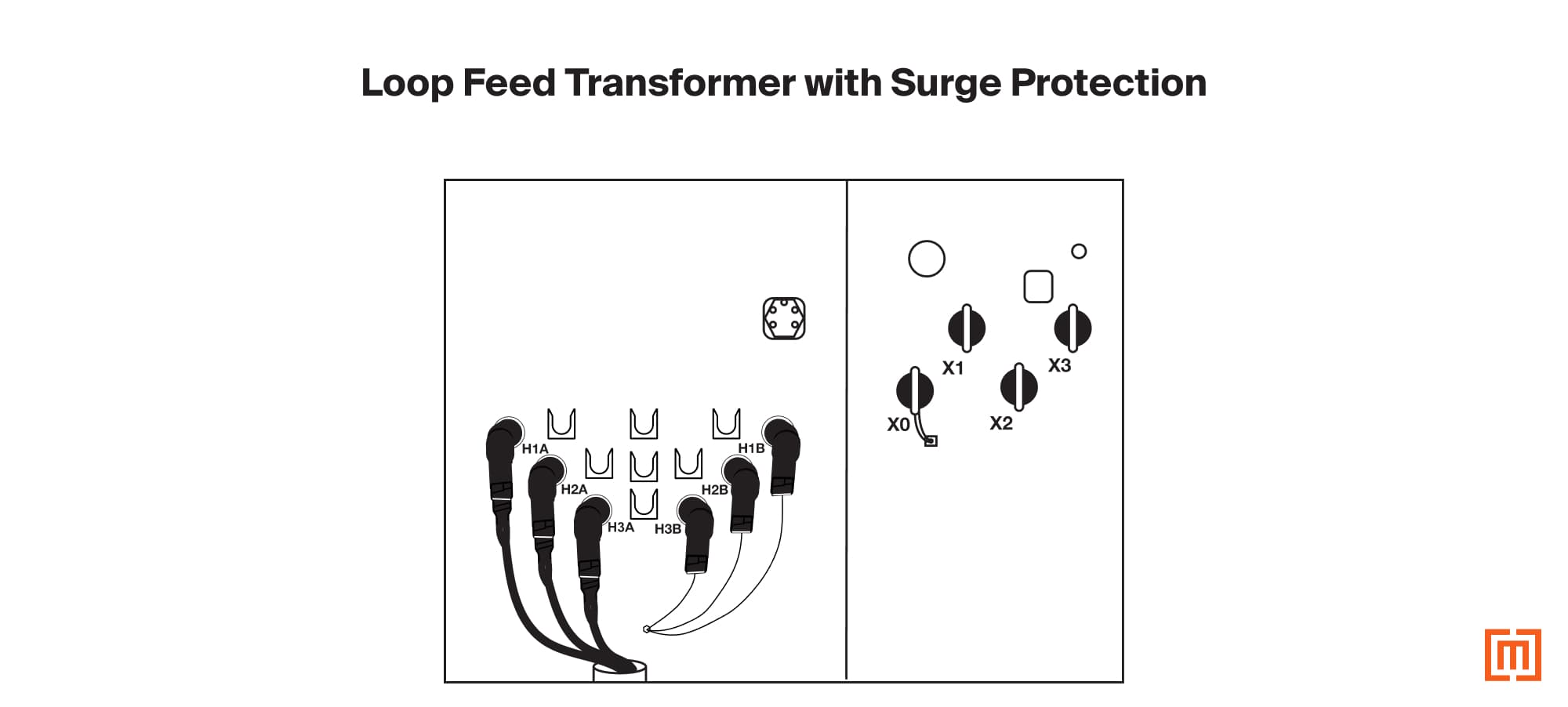
You’ll often see loop feed transformers installed in radial systems. In those cases, only one side (the A-side) is energized, while the B-side bushings are capped or fitted with elbow arresters
This is ideal for any radial feed application where only one transformer is required in an installation. Installing surge protective devices on the B-side bushings is also the standard for the last transformer in a chain or series of loop feed units.
Feed-Through Inserts
Radial feed transformers can also use rotatable feed-through inserts to add arresters or a second set of cables. This is one way of obtaining a loop feed configuration on a radial unit.
Keep in mind, the feed-through inserts on radial transformers do not allow selecting between a set of A- and B-side bushings.
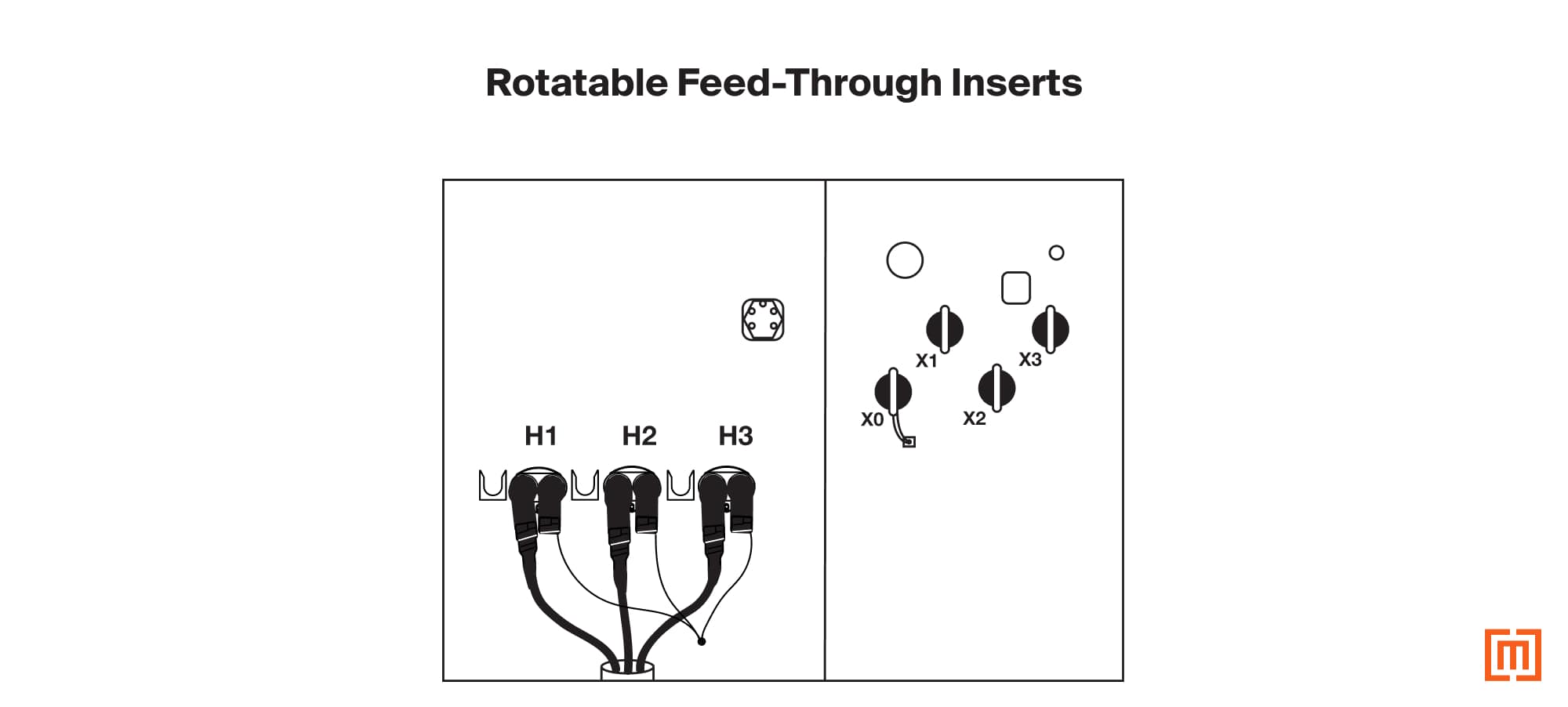
Feed-through inserts can add arresters or extend power to another transformer.
Loadbreak Selector Switches
Loop feed transformers are standard in both loop and radial systems because they can integrate oil-immersed load break switches for managing multiple source feeds.
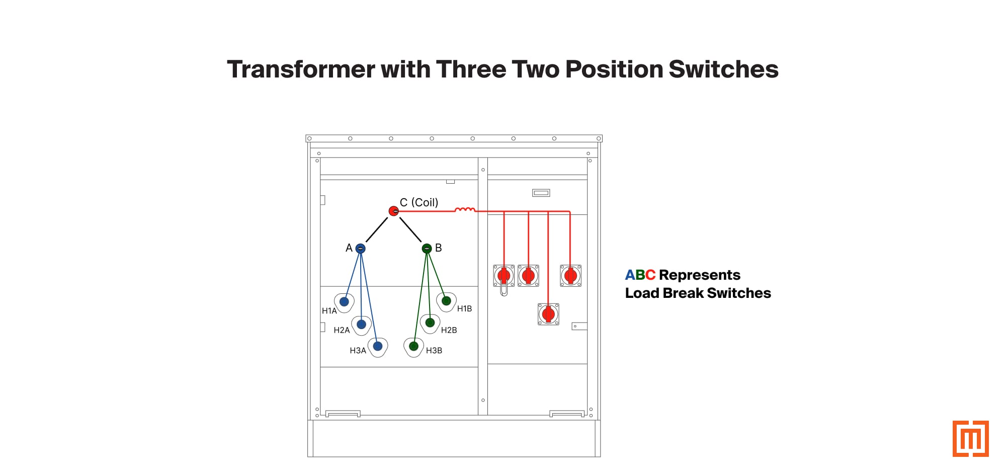
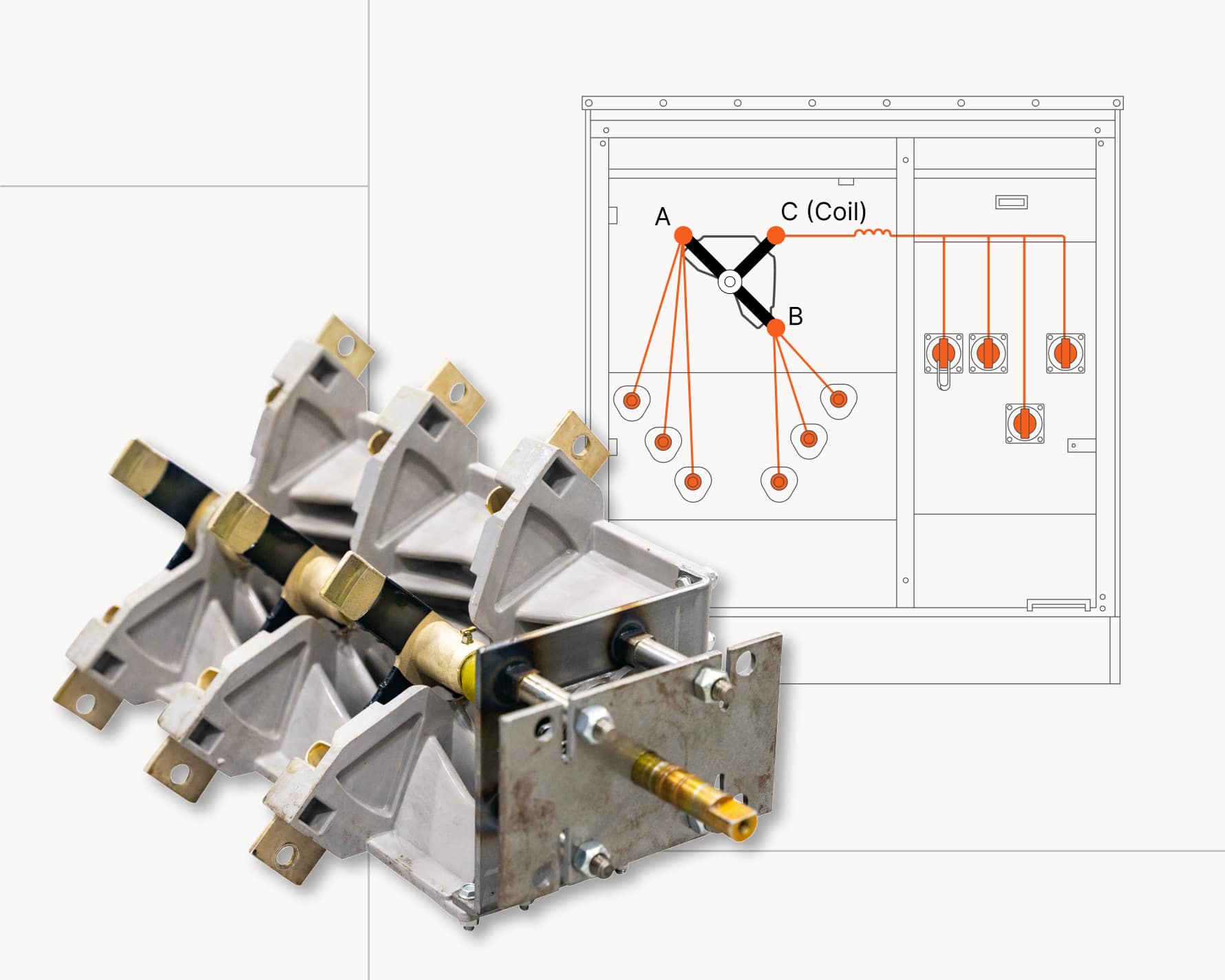
Selector switches break or redirect current between A- and B-side bushings. The most flexible setup uses three two-position switches.
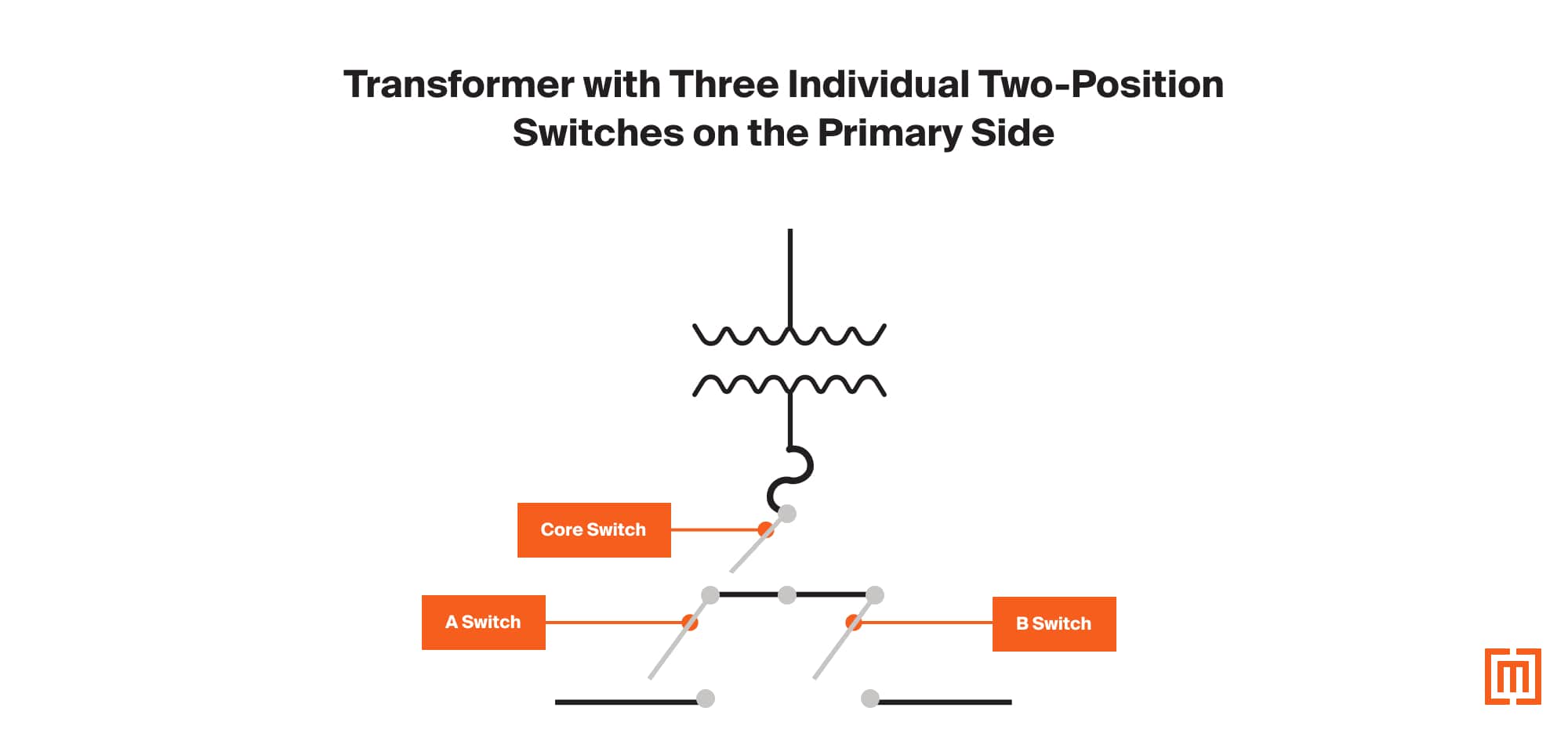
One switch controls the transformer coil. Another switch controls the A-side bushings and the last switch controls the B-side bushings.
This layout lets operators isolate or transfer load without shutting down power—ideal for both loop and multi-unit radial systems.
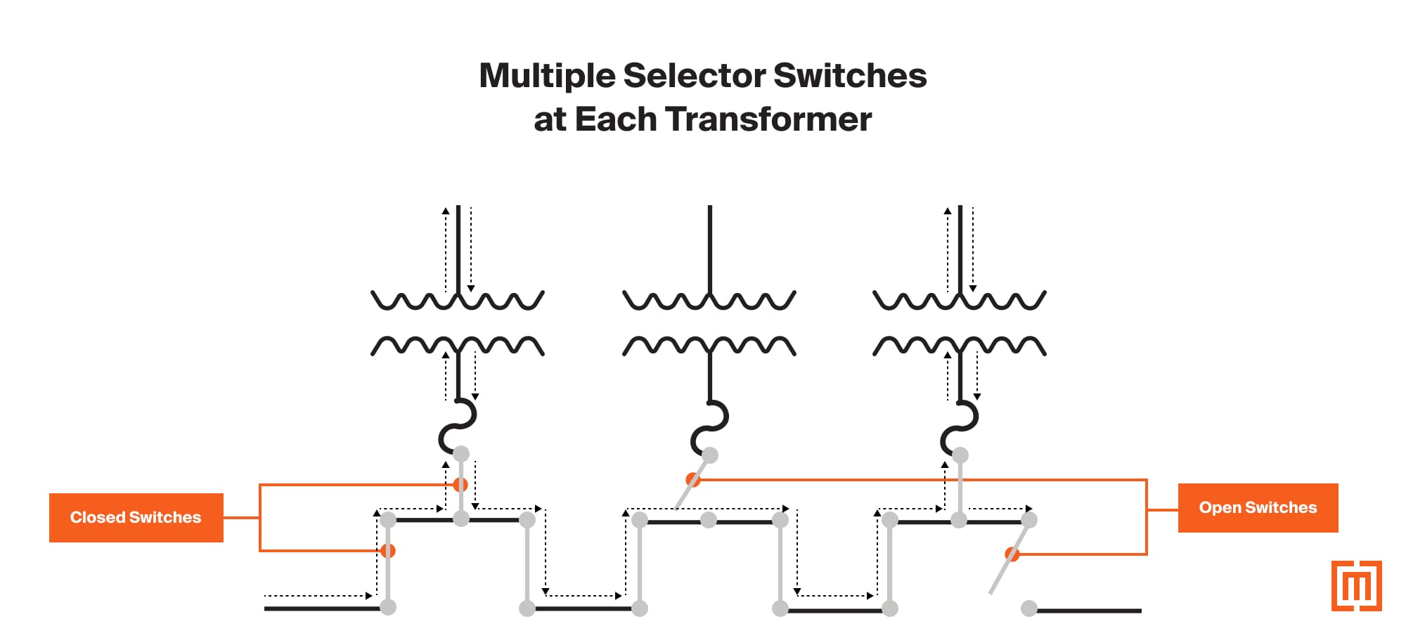
In this example, the center transformer is isolated while power continues to the others—thanks to individual selector switches at each unit.
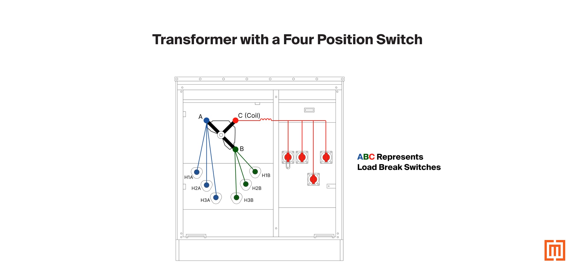
There are other possible switch configurations, such as a four-position switch–which in a way combines the three individual two-position switches into one device…with a few differences. Four position switches are also referred to as “loop feed switches” since they are exclusively used with loop feed transformers. Loop feed switches may be used in radial or loop systems.
In a radial system, they are used to isolate a transformer from others in a chain of transformers. In a loop system, such switches are more often used to control power from one of two incoming sources.
One last thing to keep in mind: four-position switches will offer only four positions. However, three two-position switches will offer more. Some projects will require limitations on the type of switch functions. Some projects need more versatility. The type of switch configuration your project requires will determine whether a four-position or multiple two-position switches work best.
Summary
As a rule of thumb, radial feed transformers, with only three primary bushings, usually indicate a radial system. And loop feed transformers can work in either type, but are almost always used in loop systems. Especially where uptime is critical (hospitals, airports, campuses, and large industrial facilities).
Loop systems rely on selector switches for source flexibility and service continuity. Radial systems are simpler, but less resilient to outages.
If you’re new to radial and loop feed padmount applications, keep this guide handy.
And if you run into specific questions or need a transformer for a particular setup, reach out. We have both loop and radial-feed transformers in stock and ready to ship! We’re always glad to help you get the right configuration for the job.


.webp)


