


Guide to Transformer Load Break Switches
A transformer load break switch (LBOR switch) turns the transformer's power on or off. Learn about 2 and 4-position switches and their different types.
How To's
Transformer load break switches enable you to turn different parts of your transformers off and on.
Let’s take a look at the basics—how these switches work, their main components, and the differences between blade styles and switch positions.
What Is a Load Break Switch?
A transformer load break switch is essentially the transformer’s on/off switch. It lets users make or break current while the transformer is energized. This allows the switch to change positions under load.
(Learn what is a transformer and how it works)
A more formal definition of a load break switch is “a disconnect switch that has been designed to provide making or breaking of specified currents.”
Something important to keep in mind: This “making or breaking” is usually done by someone using a “hot stick”. Either the local utility or a trained electrician.
In this article, we’ll look at how these switches work, the different types available, and which configurations best fit your project needs.
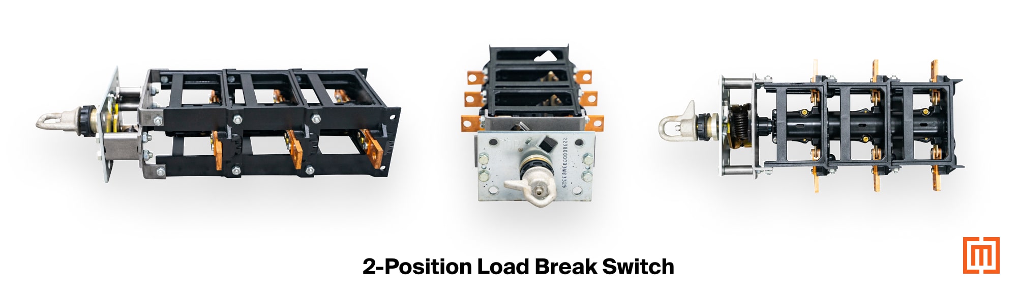
Parts of a Load Break Switch
Every load break switch shares the same basic components:
- Frame – The housing that holds the contacts and blades
- Contacts – Fixed connection points that link to the transformer’s bushings and coils
- Blades – Movable conductors that rotate to engage or disengage contacts to open or close circuits
- Shaft and Handle – The operator interface that rotates the internal shaft and blades between positions
-min.jpg)
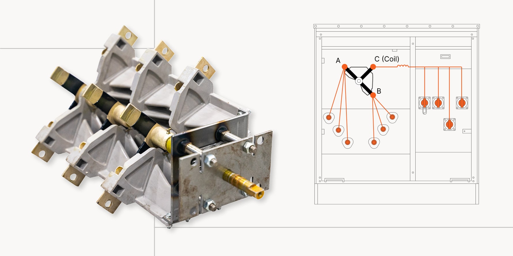
The handle extends through the transformer tank wall and connects to the rotating shaft. Turning the handle moves the blades between fixed contacts on the frame, engaging or isolating the bushings and coils. When this happens, only the blades move. That’s why it’s called a rotary-style switch.
-min.jpg)
The contact points are fixed on the frame and connect to the primary bushings and coils.
Each of these components will be energized or de-energized depending on the switch position.
Two-Position vs. Four-Position Load Break Switches
The two most common styles are two-position and four-position switches.
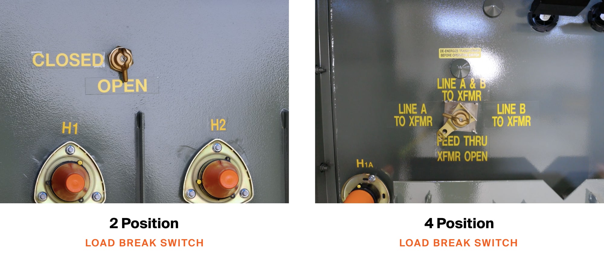
Two-Position Switches
Two-position switches have only “On” and “Off” positions. These switches are usually used in radial feed systems.
In the “Off” or “Open” position, the blades are not engaged in contacts, and there is no power flowing to the transformer windings. In the “On” or “Closed” position, the switch blades are engaged in the contacts creating a circuit to the transformer windings and secondary bushings.

Four-Position Switches
Four-position switches, usually used in loop-feed systems, allow for four configurations. Since loop-feed transformers contain six primary bushings (3 “A” side bushings and 3 “B” side bushings) a four-position load break switch gives the ability to control the bushings as well as the connection to the coil.
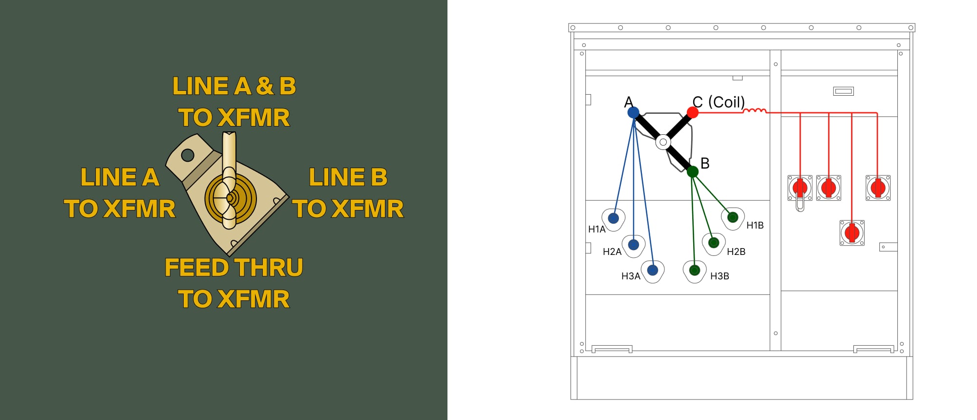
Four-Position Switch configurations
- Position 1: A & B - Coil (transformer energized)
- Position 2: B - Coil
- Position 3: A - B (Feed-through or Open)
- Position 4: A - Coil
.gif)
In Position 3 (”Feed through” or “Open”), the transformer coil is not energized. The switch type (V-blade or T-blade) will determine if it is open or feed-through in this position. Let's look at those two options.
Four-Position Switches Design: T-Blade vs. V-Blade
Four-position switches come in two designs: T-blade and V-blade.
T-Blade Switch
The T-blade gets its name from its three-armed shape. It rotates through four configurations between the bushing sides (A and B) and the coil:
T-Blade Switch Positions:
- Position 1: A & B-Coil
- Position 2: B - Coil
- Position 3: A - B (Feed-through)
- Position 4: A - Coil
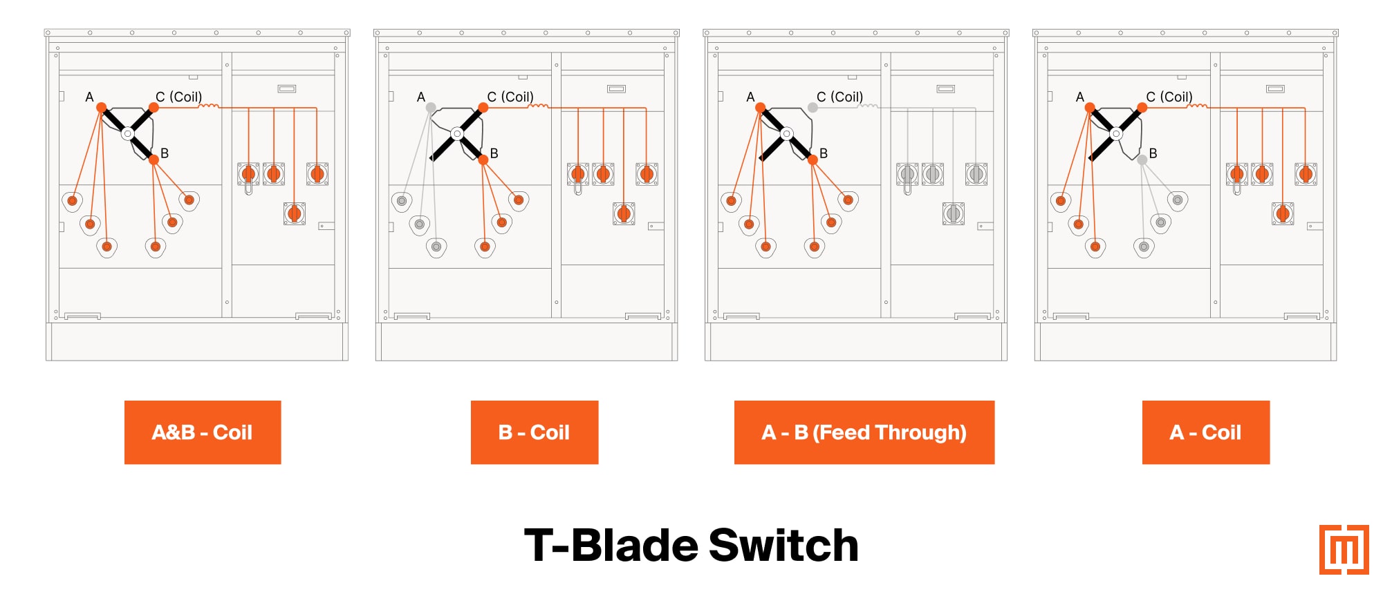
Because of its three arms, the T-blade offers a feed-through configuration (A to B direct). This position is useful when current needs to bypass the coil entirely and “feed through” to the next transformer in the loop.
-min.jpg)
V-Blade Switch
The V-blade uses two rotating arms and a fixed third conductor connected to the coil. The fixed arm keeps the coil connection available while the rotating blades engage the A and B contacts.
-min.jpg)
V-Blade Switch Positions:
- A & B - Coil
- B - Coil
- OPEN (neither A nor B connects)
- A - Coil
-min.jpg)
Differences between V-Blade and T-Blade Switches
The key difference: the V-blade has a true “Open” position that completely cuts power. While the T-blade’s feed-through means the A and B bushings stay energized–even when the coil is off.
If your project requires a guaranteed disconnect with zero current flow, choose a V-blade. If you need feed-through functionality, a T-blade may be the better fit.
Here’s a quick side-by-side comparison of the positions T-blades and V-blades offer:
Break-Before-Make vs. Make-Before-Break
Beyond blade design, another key factor is how the switch handles current during operation.
Break-Before-Make
All the switches we’ve looked at so far are what we call “break-before-make.” This means that current flow between the blade and all contact points of the switch is stopped momentarily in-between switch positions.
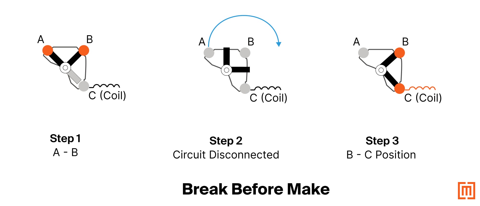
As you rotate from one position (say, A - B) to another (B - Coil), there’s a brief moment where the circuit is “broken”, and none of the blades touch the contacts. As you finish rotating the switch to the B-Coil position, the leads connect, and the circuit is “made” again.
For most systems, that’s acceptable—but in critical facilities like hospitals or data centers, even a second of power loss can cause problems.
For those scenarios, a “make before break” switch is needed.
Make-Before-Break
Make-before-break switches use a bus tie between the switch arms to maintain continuity while changing from one position to another.
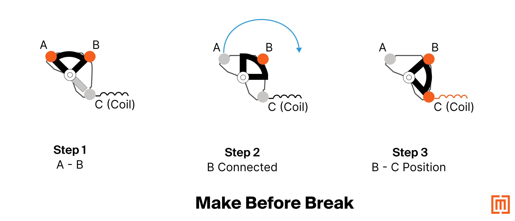
As the handle turns, the new connection briefly overlaps the old one, so power is never interrupted. These switches are essential when any outage, even brief, is unacceptable.
Both T-blade and V-blade designs can incorporate either switching method.
Conclusion
Understanding how load break switches work—and how blade type and switching style affect performance—helps ensure your transformer system runs safely and efficiently.
The right switch configuration keeps your system online and your downtime to a minimum.
Maddox has a wide range of transformers in stock with these features.
Fill out the form below to get the right load break switch for your project.


