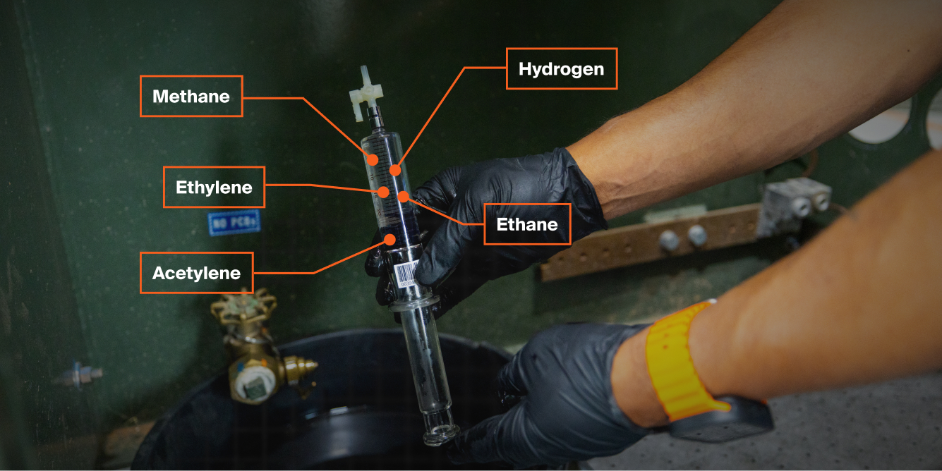
A transformer technician holding up a padmount oil sample before it is DGA tested.

How to Understand Transformer DGA Test Results

Understand transformer DGA results, including fault gases, stray gassing, overheating, partial discharge, internal arcing, and when to take action.

You’ve just got an email with the results of your transformer’s most recent DGA test. You open it. Now you’re looking at a long list of gasses and ppm values, along with some computer-generated comments.

Now what?

A Dissolved Gas Analysis (DGA) test tells you a lot about your transformer's health. But the results can be overwhelming without context.

This article will help you read those reports. We'll cover how to interpret your results, which problems create which gasses, and what to do if something looks off.

Use this as a guide, not a diagnosis. Talk to a qualified lab if you have questions about your specific transformer.

What is a Dissolved Gas Analysis (DGA) test?

A Dissolved Gas Analysis is an oil test that assesses the health of a transformer. As the oil and paper insulation inside the transformer break down, they produce gases that dissolve into the insulating fluid. A DGA test measures the concentration of these gases produced by the oil and paper. The types, concentrations, and generation rates of these gases can help identify problems such as overheating, partial discharge, atmospheric leaks, and internal arcing.

Performing this test involves drawing a sample, extracting gasses from the sample, and analyzing the gasses in a lab. 

Keep in mind that not all insulating fluids produce gasses the same way. Different fluids will produce different gasses under both fault and non-fault conditions. Since mineral oil is hydrocarbon-based, and natural esters are seed-oil based, the gas generation patterns in them will differ.

How should you interpret DGA results?

Interpreting DGA results is an involved process. And it requires looking at factors beyond the numbers on the lab report. IEEE has published standards for both mineral oil and natural esters (like FR3® Fluid) that tell you which gas levels are normal and which are not. 

However, experienced analysts also pay close attention to the rate of change between samples. They look at whether the individual gas levels increase, decrease, or stay the same from test to test. A gas level that doubles in three months is far more concerning than one that has crept up slowly over several years. (Even if the absolute value in the fast-rising case is still technically within a "normal" range.)

photo of Maddox tech holding padmount DGA sample in warehouse

When you look at your DGA test results, here are some things to keep in mind: 

Focus on trends over absolute values.

With DGA test results, context is king. Pay more attention to the trends of gas generation over time rather than the presence of a gas in a particular test. One test alone can’t tell you if active gassing is present. You’ll need at least two to three tests to really understand what’s actually happening in the transformer. 

So when should you start taking tests? You’ll want to have a solid baseline point with your data so you can clearly see what’s normal and what’s not. We recommend taking the first DGA test once you’ve received, but not energized, your transformer. Next, take another test a few months after the unit has been energized. Lastly, take a third test within the transformer’s first year of service. 

With all that test data, look for abnormal trends in the gasses. Rising, falling, and stable trends can tell you different things. A rise in fault gases indicates active gas production. Stable, non-increasing gas levels generally mean there is no fault, the fault isn’t currently active, or that it’s reached an equilibrium. 

Any excessive amount of gases is worth noting and monitoring. IEEE has several published guides (IEEE C57.166-2026) that detail which gas levels are considered normal or abnormal in a transformer. And typically, the computer labs processing your oil sample auto-generate notes based on those IEEE standards. As you take additional DGA tests, you’ll begin to see trends in the numbers that you can compare to those auto-generated notes.

Understand stray gassing.

Stray gassing is the production of dissolved gases by a transformer’s insulating fluid under normal, non-fault operating conditions. It's often mistaken for a fault indicator, since it produces the same gases that faults do.

What causes stray gassing

Stray gassing comes from slow chemical reactions in the insulating fluid itself, not from faults within the transformer. Even at normal, no fault, operating temperatures, the fluid can naturally break down as it ages. As some of the molecular bonds in the fluid break and rearrange, they can release gases like hydrogen or ethane.

This makes DGA results tricky to read. Your report may show elevated gasses that look concerning at first glance, but those gasses shouldn’t automatically be treated as evidence of arcing, overheating, or insulation failure. 

Additionally, IEEE is currently in the process of updating standards for both mineral oil and natural esters. So lab computers could be using older standards for evaluating your DGA. Between unclear sources for gasses and outdated standards for gas levels, it’s very easy to confuse a real fault with stray gassing.

Stray Gassing Example

So how do you avoid that? The best way is to get multiple sets of DGA test results to look at. For example, below is a set of sample DGA data from two padmount transformers. Both units are located on the same site and filled with FR3® Fluid.

DGA Test Data for Transformer #1

Gas Sample #5 Sample #4 Sample #3 Sample #2 Sample #1
Hydrogen 140 124 152 127 136
Methane 6 4 9 5 5
Ethane 785 679 1074 730 684
Ethylene 6 6 9 6 5
Acetylene 1 1 1 1 1
Carbon Monoxide 36 28 57 36 33
Carbon Dioxide 1,361 1,152 1,731 1,205 1,036
Nitrogen 50,579 40,561 63,368 51,682 43,004
Oxygen 444 444 444 3569 444

*Units are expressed in measurements of parts per million (ppm). 

Auto-generated comments: Hydrogen exceeds normal limits and indicates partial discharge. Ethane exceeds normal limits and indicates electrical stress or faults. 

DGA Test Data for Transformer #2

Gas Sample #5 Sample #4 Sample #3 Sample #2 Sample #1
Hydrogen 141 138 125 102 109
Methane 4 4 4 4 4
Ethane 410 382 512 370 356
Ethylene 4 4 5 4 4
Acetylene 1 1 1 1 1
Carbon Monoxide 47 42 56 39 35
Carbon Dioxide 1312 1203 1475 1091 980
Nitrogen 55281 50511 57217 50953 46554
Oxygen 444 444 444 2439 444

*Units are expressed in measurements of parts per million (ppm). 

Auto-generated comments: Hydrogen exceeds normal limits and indicates partial discharge. Ethane exceeds normal limits and indicates electrical stress or faults.

The lab flagged hydrogen and ethane in both units, since both sit above IEEE recommended limits. Even though the raw ppm numbers are different for each unit (Transformer 1 has much higher baseline ethane levels), their trends in gas generation are similar. Both show hydrogen and ethane rising, peaking at Sample 3, dropping at Sample 4, and rising again at Sample 5.

So what does this tell us? From the data sets above, we can draw at least four conclusions:

The only flagged fault gases in both units are hydrogen and ethane.

As far as other fault gasses go, we see nothing. There is no active acetylene, so no arcing or high-temperature fault is present. Both hydrogen and ethane are low-energy fault gasses that often appear in FR3® under non-fault conditions. 

The hydrogen and ethane trends in both units are similar.

What's happening in one transformer is also happening in the other. The concentration and starting point of gasses differ, but the gassing trend for both is very similar. 

It's highly unlikely that two units, with the same fluid, on the same site would show such similar trends if active faults were occurring independently in each. Occam's Razor applies here: when two explanations both fit the data, the simpler one, with fewer assumptions, is usually right. A shared, non-fault cause like stray gassing requires far fewer assumptions than two separate, coincidentally identical faults. That makes stray gassing the far more likely explanation.

The ethane particularly suggests stray gassing.

Rising ethane in both units fits the stray gassing pattern, which is more common in FR3® Fluid. That’s because FR3® Fluid is a natural ester made from vegetable oils. Its chemical make-up, especially the linolenic acid, is prone to produce stray ethane gas under normal operating conditions.

Stray Gassing often yields varying concentrations of ethane from unit to unit. The fact that one unit has significantly more ethane than the other is not concerning as long as we confirm the only issue is stray gassing.

Both the hydrogen and ethane levels are stabilizing.

Active faults (unless they are fixed or corrected) will generally yield concentrations of combustible gasses at steadily increasing levels. The production of those gasses does not usually "level off" or reach an equilibrium.

Gassing from non-fault conditions, like stray gassing, often does level off or stabilize. You’ll want to identify this in the data.

It’s important to note that stray gassing in natural esters is highly dependent on load levels and ambient weather. If the outdoor temperature and the transformer's electrical load are constantly shifting, seeing where the gassing finally levels off can be a slow and tricky process.

In the sample data, we see what could be the beginning of stabilization for both units on the second-to-last sample. The fact that the last sample rises a bit doesn’t necessarily mean it’s not leveling out. It just means there’re probably other factors extending the process. Those could be ambient temperature fluctuations or variations in load factor. 

The fact that hydrogen and ethane rise and fall concurrently in both transformers remains strong evidence that something outside the transformers is causing the gassing. Most likely stray gassing.

Alright. Let’s get back to things to think about with your own DGA test results.
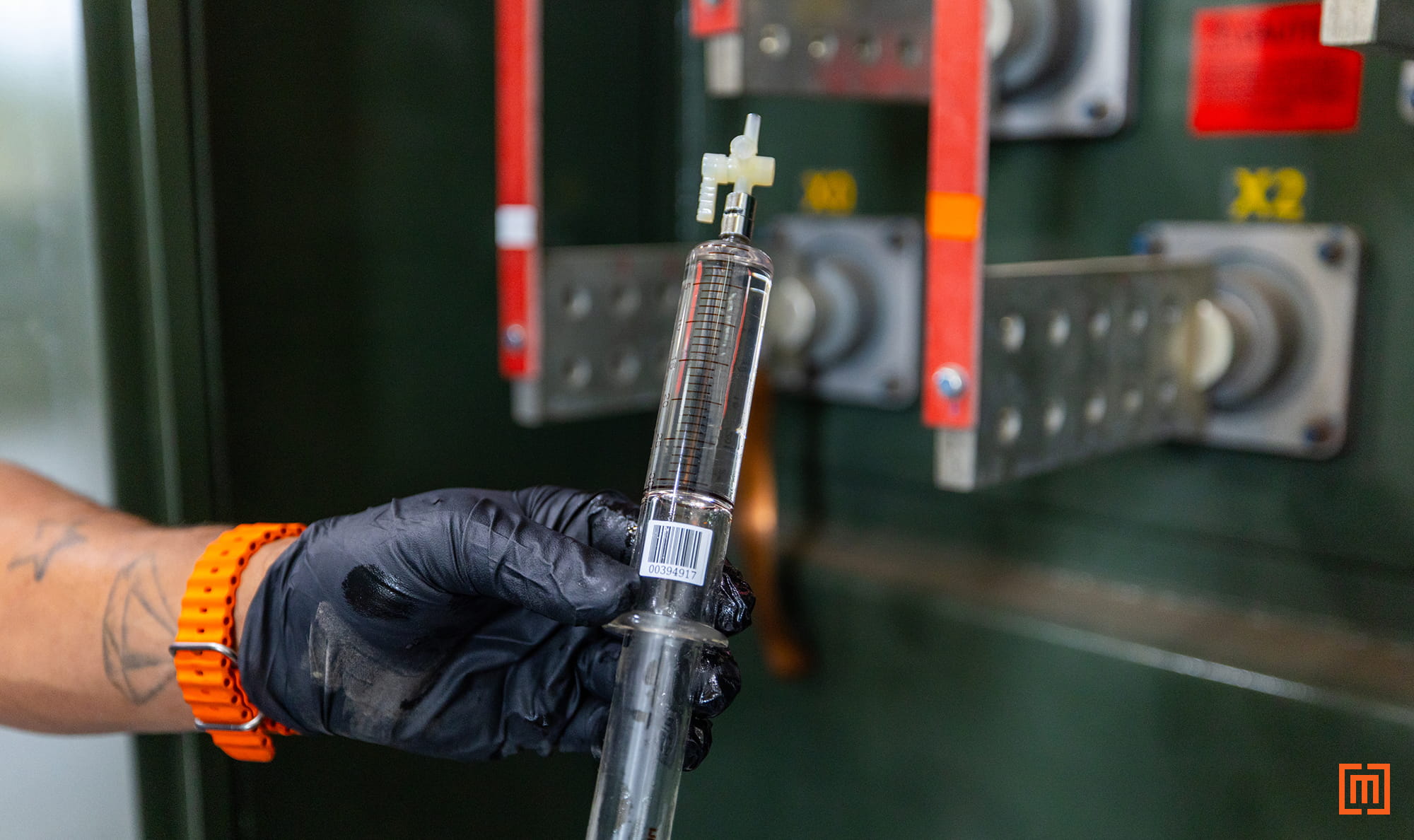
closeup photo of DGA oil sample in front of green padmount

Examine each gas in light of other gasses. 

Always look at a particular gas level in light of the other gases. Doing so can help you determine if you’re looking at stray gassing or an active fault. For example, if methane, ethylene, and acetylene levels are rising along with ethane levels, you’re probably looking at active overheating. Not stray gassing.

Remember the transformer’s age. 

Also, remember the age of the transformer. Some gasses should not show up in a brand-new unit. Or in a unit that has no history of that gas. 

If there are elevated levels of ethane in a brand-new transformer, or in a transformer that doesn’t have a history of high levels of ethane, it could be evidence of low-level overheating. You should probably test the unit again within a short amount of time just to be safe.

Use the right standard. 

IEEE guidance differs depending on the insulating fluid inside the transformer.

Historically, mineral oil results use IEEE C57.106, while natural ester fluids, such as FR3® Fluid, use IEEE C57.147. Because mineral oil has been used for much longer, significantly more historical data is available to support its diagnostic limits.

The industry is currently undergoing a major shift. IEEE is rolling out a new, consolidated guide entitled IEEE C57.166 (Acceptance and Maintenance of Insulating Liquids). Once fully published, this guide will officially replace the separate mineral oil and natural ester standards.

Talk to the experts.

Because interpretation is difficult, it was once common to evaluate gas ratios using mathematical models like the Key Gas method, Doernenburg Ratio, and Rogers Ratio. 

However, some considered these methods outdated, and they are no longer widely used. Instead, experts evaluate current gas ratios, overall fault energy, and generation trends to determine your transformer's true condition.

When the results are unclear or potentially serious, consult someone with experience interpreting DGA data.

So that’s how to interpret your DGA results. Let’s now talk about common transformer problems that produce various gasses. 

Common Transformer Scenarios and Problems

Rather than going gas by gas, we'll walk through the most common transformer problems, what causes them, and which gases show up when they happen.

Overloading and Overheating

Transformer overheating is typically caused by poor cooling, high current loads, or faulty components. These factors all cause the cellulose insulation and oil to overheat and break down. 

The resulting gasses from these breakdowns vary by fluid. In mineral oil, paper breakdown causes elevated levels of carbon monoxide, carbon dioxide, and oxygen. Oil breakdown also produces hydrogen, methane, ethane, and ethylene. (Specifically, methane and ethane are generated from mineral oil breakdown at low-to-medium temperatures. Ethylene is generated at high temperature thermal faults.) 

With natural esters, all of these gases are produced at higher amounts under non-fault conditions. Ethane is produced in significantly higher amounts under non-fault conditions in natural esters due to stray gassing.

Partial Discharge

Partial discharge is another common transformer problem. 

This low-energy fault (sometimes called corona) can happen from loose connections or conductor leads with sharp turns. On larger power transformers with higher voltage bushings, corona can develop simply due to higher field stress. 

Corona will typically generate elevated levels of hydrogen and methane. Hydrogen begins to form from the breakdown of mineral oil at around 150°C, but it can also be produced from paper insulation, or when water interacts with rust or galvanized metals inside the tank. You may see higher levels of hydrogen in natural esters under normal conditions.

Atmospheric Leaks

Broken gaskets or compromised seals around the tank allow outside air to enter the transformer. If you do have an atmospheric leak, you’ll see elevated levels of oxygen in the test results. Oxygen and nitrogen are atmospheric, non-combustible gasses that come from the air outside the transformer, and are tracked to verify the integrity of the transformer's oil preservation system. The ratio of both gasses can indicate whether there’s an air leak or not.

Internal Arcing

Internal arcing is one of the biggest transformer concerns. 

Severe system failures can expose the transformer to high overcurrents which can then cause arcing. Poor connections inside the unit can also cause arcing. If arcing occurs, acetylene will show up in your results. 

The presence of acetylene should always be investigated, especially if the concentration is both high and increasing. Active arcing occurring in the oil will produce oil breakdown gasses, while arcing near the paper insulation will produce high amounts of carbon gasses. 

Note that trace amounts of acetylene are sometimes present under non-fault conditions. Small acetylene amounts could come from the welding process for newly-built transformers. Or they could come from the normal operation of loadbreak switches.

Alright. We’ve discussed guidelines for interpreting DGA test results. And we’ve broken down which transformer problems create which common gasses. 

So let’s say you’ve reviewed the DGA results...and it does look like there’s a problem. What do you do next?
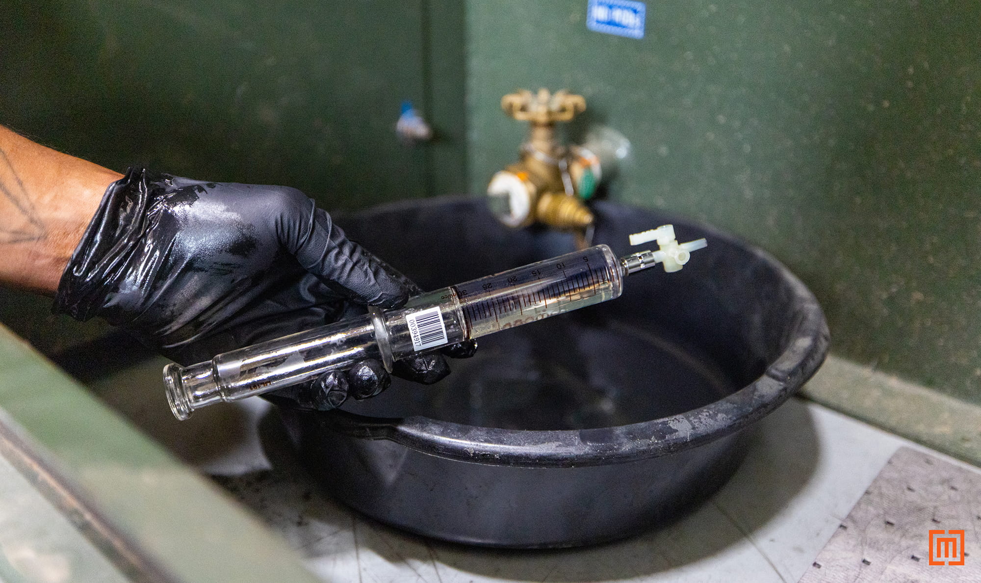
closeup of DGA sample resting on oil drip pan in green padmount cabinet

What to Do When Results Are Concerning

If a DGA report comes back showing elevated or rapidly rising combustible gases, follow the steps below.

Take another test. 

If a standalone set of DGA results is concerning, you’ll want to get a second sample so you have at least two sets of data to evaluate for trends. The severity of the issue flagged in the first DGA will determine how soon you should take the second test. Once you have two to three sets of test data, you should have a clearer understanding of whether the transformer can continue in service.

Maintain or repair the transformer. 

Depending on the test results, the transformer may continue operating safely under observation. Or, you may need to de-energize it for either additional testing or repairs.

Resist "band-aid" fixes.

If your transformer has a problem, it’s very important to avoid any "band-aid" fixes. Some folks will pay a lot of money to de-gas a transformer without ever addressing the underlying problems. However, simply degassing the oil will not fix the physical fault that is generating the gasses. If that’s all you do, you can expect the problem to continue.
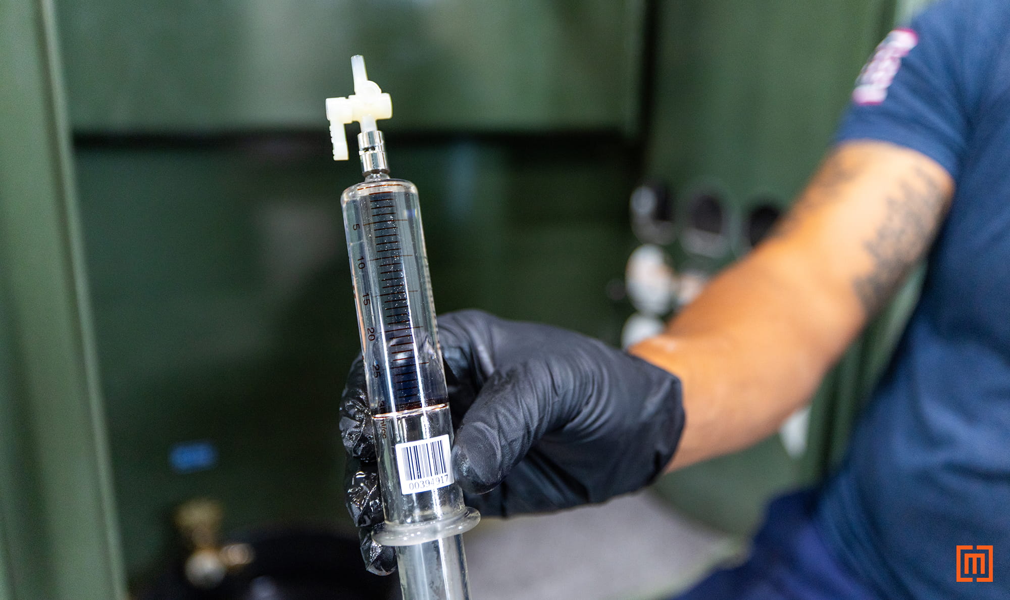
closeup of tech holding DGA sample in front of green padmount in warehousee

DGA Testing Takeaways

Dissolved Gas Analysis gives you a valuable picture of what's happening inside your liquid-filled transformer. It can catch early signs of insulation breakdown, overheating, partial discharge, air leaks, and arcing.

If your DGA test results indicate your unit needs a repair, rewind, or inspection, fill out the form below.

Written by:
Matt Estelle, Ben Gulick, and Miles Whitling
A Maddox Padmount transformer loaded on a truck and shipping out

Get in touch

Find out how Maddox can power on your next project.
Thank you!
Your submission has been received!
Oops! Something went wrong while submitting the form.
All Articles

How to Understand Transformer DGA Test Results

Understand transformer DGA results, including fault gases, stray gassing, overheating, partial discharge, internal arcing, and when to take action.

Written by:
Matt Estelle, Ben Gulick, and Miles Whitling

August 14, 2026

A transformer technician holding up a padmount oil sample before it is DGA tested.

You’ve just got an email with the results of your transformer’s most recent DGA test. You open it. Now you’re looking at a long list of gasses and ppm values, along with some computer-generated comments.

Now what?

A Dissolved Gas Analysis (DGA) test tells you a lot about your transformer's health. But the results can be overwhelming without context.

This article will help you read those reports. We'll cover how to interpret your results, which problems create which gasses, and what to do if something looks off.

Use this as a guide, not a diagnosis. Talk to a qualified lab if you have questions about your specific transformer.

What is a Dissolved Gas Analysis (DGA) test?

A Dissolved Gas Analysis is an oil test that assesses the health of a transformer. As the oil and paper insulation inside the transformer break down, they produce gases that dissolve into the insulating fluid. A DGA test measures the concentration of these gases produced by the oil and paper. The types, concentrations, and generation rates of these gases can help identify problems such as overheating, partial discharge, atmospheric leaks, and internal arcing.

Performing this test involves drawing a sample, extracting gasses from the sample, and analyzing the gasses in a lab. 

Keep in mind that not all insulating fluids produce gasses the same way. Different fluids will produce different gasses under both fault and non-fault conditions. Since mineral oil is hydrocarbon-based, and natural esters are seed-oil based, the gas generation patterns in them will differ.

How should you interpret DGA results?

Interpreting DGA results is an involved process. And it requires looking at factors beyond the numbers on the lab report. IEEE has published standards for both mineral oil and natural esters (like FR3® Fluid) that tell you which gas levels are normal and which are not. 

However, experienced analysts also pay close attention to the rate of change between samples. They look at whether the individual gas levels increase, decrease, or stay the same from test to test. A gas level that doubles in three months is far more concerning than one that has crept up slowly over several years. (Even if the absolute value in the fast-rising case is still technically within a "normal" range.)

photo of Maddox tech holding padmount DGA sample in warehouse

When you look at your DGA test results, here are some things to keep in mind: 

Focus on trends over absolute values.

With DGA test results, context is king. Pay more attention to the trends of gas generation over time rather than the presence of a gas in a particular test. One test alone can’t tell you if active gassing is present. You’ll need at least two to three tests to really understand what’s actually happening in the transformer. 

So when should you start taking tests? You’ll want to have a solid baseline point with your data so you can clearly see what’s normal and what’s not. We recommend taking the first DGA test once you’ve received, but not energized, your transformer. Next, take another test a few months after the unit has been energized. Lastly, take a third test within the transformer’s first year of service. 

With all that test data, look for abnormal trends in the gasses. Rising, falling, and stable trends can tell you different things. A rise in fault gases indicates active gas production. Stable, non-increasing gas levels generally mean there is no fault, the fault isn’t currently active, or that it’s reached an equilibrium. 

Any excessive amount of gases is worth noting and monitoring. IEEE has several published guides (IEEE C57.166-2026) that detail which gas levels are considered normal or abnormal in a transformer. And typically, the computer labs processing your oil sample auto-generate notes based on those IEEE standards. As you take additional DGA tests, you’ll begin to see trends in the numbers that you can compare to those auto-generated notes.

Understand stray gassing.

Stray gassing is the production of dissolved gases by a transformer’s insulating fluid under normal, non-fault operating conditions. It's often mistaken for a fault indicator, since it produces the same gases that faults do.

What causes stray gassing

Stray gassing comes from slow chemical reactions in the insulating fluid itself, not from faults within the transformer. Even at normal, no fault, operating temperatures, the fluid can naturally break down as it ages. As some of the molecular bonds in the fluid break and rearrange, they can release gases like hydrogen or ethane.

This makes DGA results tricky to read. Your report may show elevated gasses that look concerning at first glance, but those gasses shouldn’t automatically be treated as evidence of arcing, overheating, or insulation failure. 

Additionally, IEEE is currently in the process of updating standards for both mineral oil and natural esters. So lab computers could be using older standards for evaluating your DGA. Between unclear sources for gasses and outdated standards for gas levels, it’s very easy to confuse a real fault with stray gassing.

Stray Gassing Example

So how do you avoid that? The best way is to get multiple sets of DGA test results to look at. For example, below is a set of sample DGA data from two padmount transformers. Both units are located on the same site and filled with FR3® Fluid.

DGA Test Data for Transformer #1

Gas Sample #5 Sample #4 Sample #3 Sample #2 Sample #1
Hydrogen 140 124 152 127 136
Methane 6 4 9 5 5
Ethane 785 679 1074 730 684
Ethylene 6 6 9 6 5
Acetylene 1 1 1 1 1
Carbon Monoxide 36 28 57 36 33
Carbon Dioxide 1,361 1,152 1,731 1,205 1,036
Nitrogen 50,579 40,561 63,368 51,682 43,004
Oxygen 444 444 444 3569 444

*Units are expressed in measurements of parts per million (ppm). 

Auto-generated comments: Hydrogen exceeds normal limits and indicates partial discharge. Ethane exceeds normal limits and indicates electrical stress or faults. 

DGA Test Data for Transformer #2

Gas Sample #5 Sample #4 Sample #3 Sample #2 Sample #1
Hydrogen 141 138 125 102 109
Methane 4 4 4 4 4
Ethane 410 382 512 370 356
Ethylene 4 4 5 4 4
Acetylene 1 1 1 1 1
Carbon Monoxide 47 42 56 39 35
Carbon Dioxide 1312 1203 1475 1091 980
Nitrogen 55281 50511 57217 50953 46554
Oxygen 444 444 444 2439 444

*Units are expressed in measurements of parts per million (ppm). 

Auto-generated comments: Hydrogen exceeds normal limits and indicates partial discharge. Ethane exceeds normal limits and indicates electrical stress or faults.

The lab flagged hydrogen and ethane in both units, since both sit above IEEE recommended limits. Even though the raw ppm numbers are different for each unit (Transformer 1 has much higher baseline ethane levels), their trends in gas generation are similar. Both show hydrogen and ethane rising, peaking at Sample 3, dropping at Sample 4, and rising again at Sample 5.

So what does this tell us? From the data sets above, we can draw at least four conclusions:

The only flagged fault gases in both units are hydrogen and ethane.

As far as other fault gasses go, we see nothing. There is no active acetylene, so no arcing or high-temperature fault is present. Both hydrogen and ethane are low-energy fault gasses that often appear in FR3® under non-fault conditions. 

The hydrogen and ethane trends in both units are similar.

What's happening in one transformer is also happening in the other. The concentration and starting point of gasses differ, but the gassing trend for both is very similar. 

It's highly unlikely that two units, with the same fluid, on the same site would show such similar trends if active faults were occurring independently in each. Occam's Razor applies here: when two explanations both fit the data, the simpler one, with fewer assumptions, is usually right. A shared, non-fault cause like stray gassing requires far fewer assumptions than two separate, coincidentally identical faults. That makes stray gassing the far more likely explanation.

The ethane particularly suggests stray gassing.

Rising ethane in both units fits the stray gassing pattern, which is more common in FR3® Fluid. That’s because FR3® Fluid is a natural ester made from vegetable oils. Its chemical make-up, especially the linolenic acid, is prone to produce stray ethane gas under normal operating conditions.

Stray Gassing often yields varying concentrations of ethane from unit to unit. The fact that one unit has significantly more ethane than the other is not concerning as long as we confirm the only issue is stray gassing.

Both the hydrogen and ethane levels are stabilizing.

Active faults (unless they are fixed or corrected) will generally yield concentrations of combustible gasses at steadily increasing levels. The production of those gasses does not usually "level off" or reach an equilibrium.

Gassing from non-fault conditions, like stray gassing, often does level off or stabilize. You’ll want to identify this in the data.

It’s important to note that stray gassing in natural esters is highly dependent on load levels and ambient weather. If the outdoor temperature and the transformer's electrical load are constantly shifting, seeing where the gassing finally levels off can be a slow and tricky process.

In the sample data, we see what could be the beginning of stabilization for both units on the second-to-last sample. The fact that the last sample rises a bit doesn’t necessarily mean it’s not leveling out. It just means there’re probably other factors extending the process. Those could be ambient temperature fluctuations or variations in load factor. 

The fact that hydrogen and ethane rise and fall concurrently in both transformers remains strong evidence that something outside the transformers is causing the gassing. Most likely stray gassing.

Alright. Let’s get back to things to think about with your own DGA test results.

closeup photo of DGA oil sample in front of green padmount

Examine each gas in light of other gasses. 

Always look at a particular gas level in light of the other gases. Doing so can help you determine if you’re looking at stray gassing or an active fault. For example, if methane, ethylene, and acetylene levels are rising along with ethane levels, you’re probably looking at active overheating. Not stray gassing.

Remember the transformer’s age. 

Also, remember the age of the transformer. Some gasses should not show up in a brand-new unit. Or in a unit that has no history of that gas. 

If there are elevated levels of ethane in a brand-new transformer, or in a transformer that doesn’t have a history of high levels of ethane, it could be evidence of low-level overheating. You should probably test the unit again within a short amount of time just to be safe.

Use the right standard. 

IEEE guidance differs depending on the insulating fluid inside the transformer.

Historically, mineral oil results use IEEE C57.106, while natural ester fluids, such as FR3® Fluid, use IEEE C57.147. Because mineral oil has been used for much longer, significantly more historical data is available to support its diagnostic limits.

The industry is currently undergoing a major shift. IEEE is rolling out a new, consolidated guide entitled IEEE C57.166 (Acceptance and Maintenance of Insulating Liquids). Once fully published, this guide will officially replace the separate mineral oil and natural ester standards.

Talk to the experts.

Because interpretation is difficult, it was once common to evaluate gas ratios using mathematical models like the Key Gas method, Doernenburg Ratio, and Rogers Ratio. 

However, some considered these methods outdated, and they are no longer widely used. Instead, experts evaluate current gas ratios, overall fault energy, and generation trends to determine your transformer's true condition.

When the results are unclear or potentially serious, consult someone with experience interpreting DGA data.

So that’s how to interpret your DGA results. Let’s now talk about common transformer problems that produce various gasses. 

Common Transformer Scenarios and Problems

Rather than going gas by gas, we'll walk through the most common transformer problems, what causes them, and which gases show up when they happen.

Overloading and Overheating

Transformer overheating is typically caused by poor cooling, high current loads, or faulty components. These factors all cause the cellulose insulation and oil to overheat and break down. 

The resulting gasses from these breakdowns vary by fluid. In mineral oil, paper breakdown causes elevated levels of carbon monoxide, carbon dioxide, and oxygen. Oil breakdown also produces hydrogen, methane, ethane, and ethylene. (Specifically, methane and ethane are generated from mineral oil breakdown at low-to-medium temperatures. Ethylene is generated at high temperature thermal faults.) 

With natural esters, all of these gases are produced at higher amounts under non-fault conditions. Ethane is produced in significantly higher amounts under non-fault conditions in natural esters due to stray gassing.

Partial Discharge

Partial discharge is another common transformer problem. 

This low-energy fault (sometimes called corona) can happen from loose connections or conductor leads with sharp turns. On larger power transformers with higher voltage bushings, corona can develop simply due to higher field stress. 

Corona will typically generate elevated levels of hydrogen and methane. Hydrogen begins to form from the breakdown of mineral oil at around 150°C, but it can also be produced from paper insulation, or when water interacts with rust or galvanized metals inside the tank. You may see higher levels of hydrogen in natural esters under normal conditions.

Atmospheric Leaks

Broken gaskets or compromised seals around the tank allow outside air to enter the transformer. If you do have an atmospheric leak, you’ll see elevated levels of oxygen in the test results. Oxygen and nitrogen are atmospheric, non-combustible gasses that come from the air outside the transformer, and are tracked to verify the integrity of the transformer's oil preservation system. The ratio of both gasses can indicate whether there’s an air leak or not.

Internal Arcing

Internal arcing is one of the biggest transformer concerns. 

Severe system failures can expose the transformer to high overcurrents which can then cause arcing. Poor connections inside the unit can also cause arcing. If arcing occurs, acetylene will show up in your results. 

The presence of acetylene should always be investigated, especially if the concentration is both high and increasing. Active arcing occurring in the oil will produce oil breakdown gasses, while arcing near the paper insulation will produce high amounts of carbon gasses. 

Note that trace amounts of acetylene are sometimes present under non-fault conditions. Small acetylene amounts could come from the welding process for newly-built transformers. Or they could come from the normal operation of loadbreak switches.

Alright. We’ve discussed guidelines for interpreting DGA test results. And we’ve broken down which transformer problems create which common gasses. 

So let’s say you’ve reviewed the DGA results...and it does look like there’s a problem. What do you do next?

closeup of DGA sample resting on oil drip pan in green padmount cabinet

What to Do When Results Are Concerning

If a DGA report comes back showing elevated or rapidly rising combustible gases, follow the steps below.

Take another test. 

If a standalone set of DGA results is concerning, you’ll want to get a second sample so you have at least two sets of data to evaluate for trends. The severity of the issue flagged in the first DGA will determine how soon you should take the second test. Once you have two to three sets of test data, you should have a clearer understanding of whether the transformer can continue in service.

Maintain or repair the transformer. 

Depending on the test results, the transformer may continue operating safely under observation. Or, you may need to de-energize it for either additional testing or repairs.

Resist "band-aid" fixes.

If your transformer has a problem, it’s very important to avoid any "band-aid" fixes. Some folks will pay a lot of money to de-gas a transformer without ever addressing the underlying problems. However, simply degassing the oil will not fix the physical fault that is generating the gasses. If that’s all you do, you can expect the problem to continue.

closeup of tech holding DGA sample in front of green padmount in warehousee

DGA Testing Takeaways

Dissolved Gas Analysis gives you a valuable picture of what's happening inside your liquid-filled transformer. It can catch early signs of insulation breakdown, overheating, partial discharge, air leaks, and arcing.

If your DGA test results indicate your unit needs a repair, rewind, or inspection, fill out the form below.

A Maddox Padmount transformer loaded on a truck and shipping out

Get in touch

Find out how Maddox can power on your next project.
Thank you!
Your submission has been received!
Oops! Something went wrong while submitting the form.