.jpg)


Guide to Transformer Testing Standards
Overview of the common tests performed on transformers, including Winding Resistance, Megger, Transformer Turns Ratio, Load-Loss, Leak Tests, and others.
How To's
This article provides a list of the standard tests performed on new and remanufactured transformers. It covers the purpose and scope of the most common routine factory and diagnostic field tests.
Factory testing for liquid-filled transformers (padmounts and substations) follows IEEE C57.12.00 and IEEE C57.12.90 standards and IEEE C57.12.01 and IEEE C57.12.91 standards for dry-type transformers.
Types of Transformer Test
(as defined in IEEE C57.12.80-2002)
Routine Tests
The purpose of routine testing is quality control. These tests are performed in the final stages of manufacturing for all new factory-built transformers. These tests are also referred to as pass/fail.
IEEE C57.12.00 & IEEE C57.12.90 (Liquid-Immersed)
IEEE C57.12.01 & IEEE C57.12.91 (Dry-Type)
Design Tests
Design tests are performed on the first unit of a particular design to make sure units meet their assigned ratings. These tests confirm operation under normal service conditions, or special conditions when specified. They also show compliance with industry standards.
IEEE C57.12.00 & IEEE C57.12.90 (Liquid-Immersed)
IEEE C57.12.01 & IEEE C57.12.91 (Dry-Type)
Other Transformer Tests
In addition to standard tests, Maddox frequently performs specific diagnostic tests on select units. Such tests fall into the “other” IEEE category. These tests are called out in user product standards (though not required by IEEE). They also may be specified by the purchasers to be performed in addition to design and routine tests.
IEEE C57.12.00 & IEEE C57.12.90 (Liquid-Immersed)
Common Transformer Tests
Let’s take a closer look at some of the tests that we’ve outlined above. We’ll look at some that are routine, some that are design, and some that are other.
Transformer Turns Ratio (TTR)
Routine Test for All Transformers
The transformer turns ratio test tells you whether a transformer’s tested ratio is close enough to the unit’s calculated value per IEEE standards.
Every two-winding transformer has a ratio. The ratio is the relationship between the number of turns on the primary and secondary windings of a transformer. To understand the basic function of a transformer, you could think of it as a ratio box. No matter what voltage you put into it, the output voltage will always be proportional to the input.
An example of a 1:1 ratio would be where the input and output voltages are the same (for every 1 turn on the primary winding, you would have 1 corresponding turn on the secondary). For a 2:1 ratio, the secondary (output) voltage is half of the primary (input) voltage—for every two turns on the primary winding, you have one corresponding turn on the secondary side, and so on. If you applied 10 volts to the primary of a transformer with a 2:1 ratio, the result would be 5 volts on the secondary; if you put 20 volts into the same transformer, you would get 10 volts out.
This predetermined relationship between the primary and secondary windings for any given transformer is called the calculated ratio. The turns ratio test (TTR) is performed to confirm that the unit’s tested ratio lies close enough to the calculated value per IEEE standards.
To find the calculated ratio, divide the rated primary phase voltage by the rated secondary phase voltage as depicted on the nameplate. When determining the calculated ratio, it is important to refer to the coil (phase) voltage—the phase voltage determines the number of turns at the transformer coils.
For a delta-connected winding, the phase voltage is the same as the line-to-line voltage, but for a wye-connected winding, the line and phase voltages are different. For a wye winding, the phase voltage is represented by the second smaller number (line-to-neutral) and is obtained by dividing the phase-to-phase voltage by the square root of 3 and is written as follows: 13200 Y/ 7620. For example, a transformer that is 13200 Y/ 7620 - 480 Y/ 277 would have a calculated ratio of 27.51, whereas a 13200 D - 480 Y/ 277 would have a calculated ratio of 47.65.
When a transformer is built at the factory, the actual ratio at the coils will differ slightly from the calculated value due mainly to the fact that you cannot have partial turns. IEEE standards allow a 0.5% variance above and below the calculated value for tested ratios. This standard is used by Maddox, and it is the same standard employed by NETA field testing companies.
Maddox performs a standard TTR test on all used units twice–once when the units are brought into inventory, and again after the remanufacturing process is complete. Test values are provided for all available tap positions on remanufactured units.
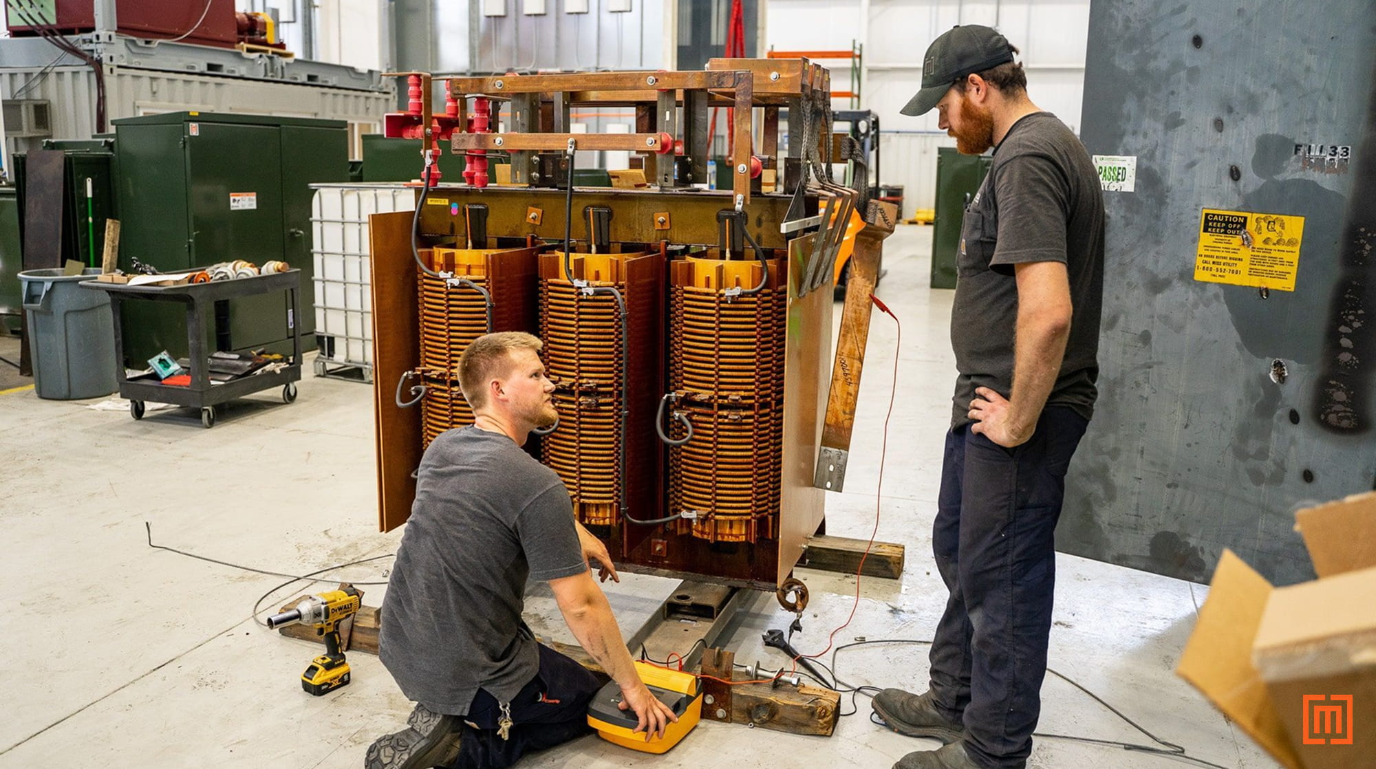
Winding Resistance
Routine Test for > 2500 kVA Transformers
Design Test for units ≤ 2500 kVA Transformers
A winding resistance test helps evaluate the condition and quality of the current-carrying path of the windings in a transformer.
This test is performed for all new factory-built padmount transformers above 2,500 kVA (IEEE C57.12.00). Maddox, however, utilizes the winding resistance test for all remanufactured medium-voltage units. Winding resistance provides helpful diagnostic information which can aid in evaluating whether a unit is suitable for repair or remanufacturing. Issues such as loose internal connections, faulty tap changers, open circuits, and broken conductor strands or crimp connections may be identified with this test.
In the case of a delta connection, measurements are made phase-to-phase (H1-H2, H2-H3, H1-H3). With a wye connection, measurements may also be made phase-to-phase (H1-H2, H2-H3, H1-H3), as well as phase-to-neutral (H1-H0, H2-H0, H3-H0).
This test is measured in ohms, and the value is typically low (tenths or hundredths of a decimal). Keep in mind that when this test is performed (especially in the field), it is typically done at the bushings of the transformer. As a result, measurements will include any components in the current-carrying path of the windings, such as tap changers, fuses, switches, and cable leads, which may affect test results.

A questionable reading may not always indicate a problem. For instance, if one phase of a transformer has a longer section of internal bus work between the bushing and the winding lead it connects to, you may see a higher measured value across that particular phase. In this case, the test data doesn’t indicate a problem. Just the factory design of the unit.
But, you could get similar results from a loose or bad connection too. Judging the difference usually requires a previous test to compare with.
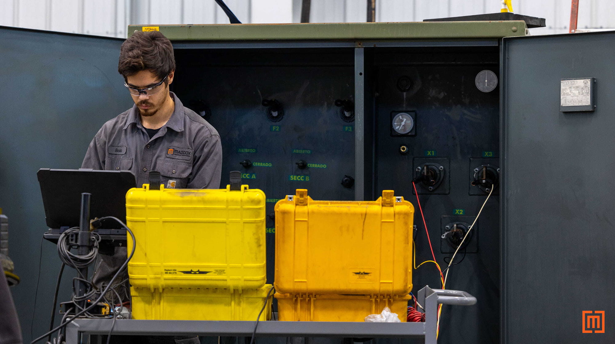
Insulation Resistance (Megger)
Other Test for Distribution Transformers
Insulation resistance (IR) testing is a helpful diagnostic test. Like winding resistance, it’s measured in ohms. But, unlike winding resistance, IR measures the condition of the transformer’s insulation between windings and core ground. The test is performed by applying a specified DC voltage through the transformer’s conductors.
Why perform this test? Over time, the insulation may weaken from factors such as overheating, aging or moisture. Weak or compromised insulation can lead to short circuits and winding failures. The best way to check for insulation problems is to log several IR tests over time. An initial test gives you a baseline to test to in the future. If a subsequent test shows a lower reading, it could indicate a problem.
Keep in mind, first-time test results will vary widely between transformers. Core grounding methods and factors such as switches, fuses, tap-changers, and fluids may also affect test results. While this test is not usually used for quality control in the factory, questionable results should be carefully evaluated before a transformer is approved for service. When field testing, it is important to consult the manufacturer for the values they consider passing. Insulation resistance is performed on the high-side windings to low-side windings, high-side windings to ground, and low-side windings to ground.
Maddox performs insulation resistance testing twice for all remanufactured transformers. Once upon receipt, and then again after the remanufacturing process.
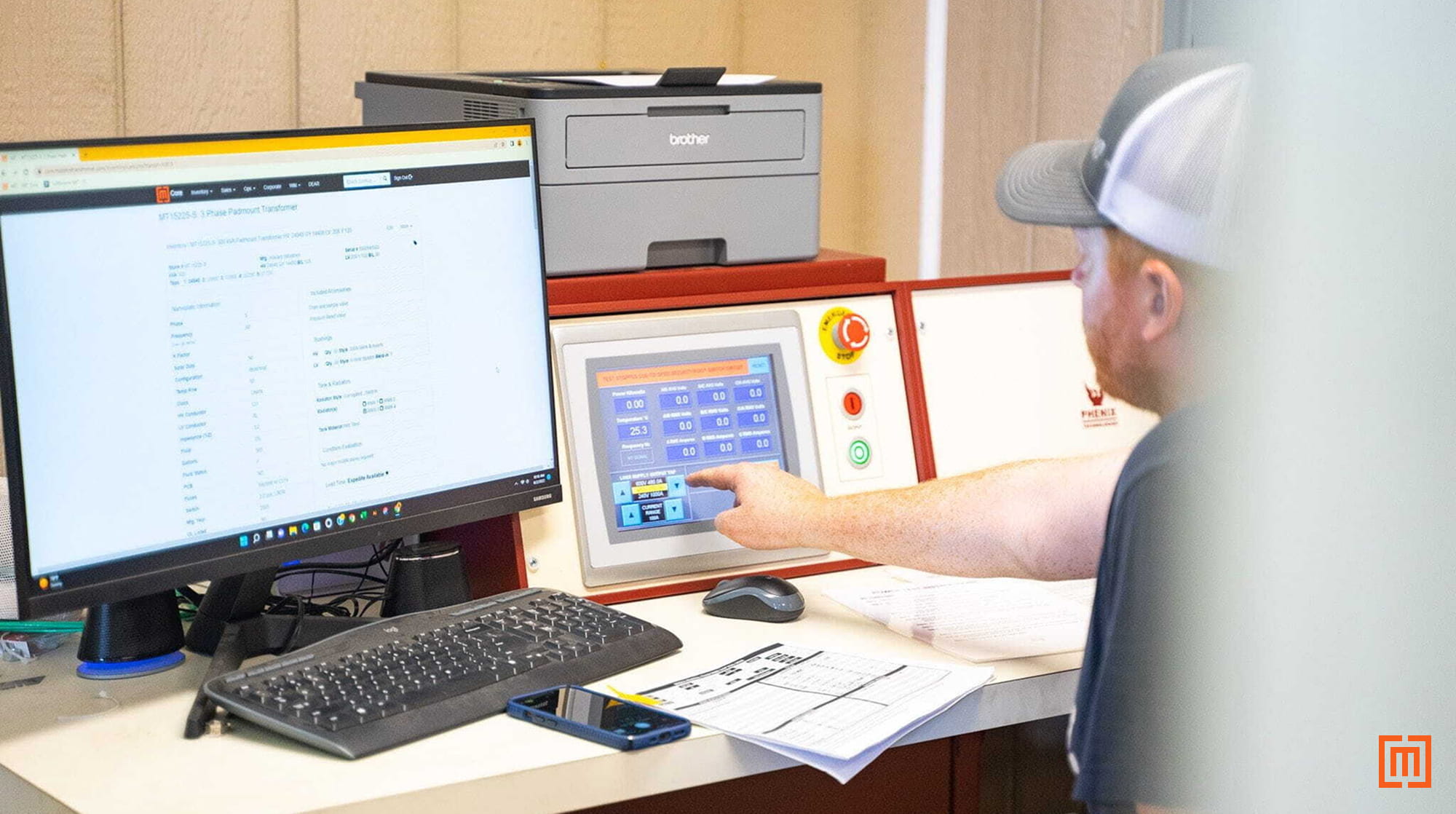
Impedance Voltage (Positive Sequence), Load Loss
Routine Test for All Transformers
The impedance test measures how much power is lost during electrical operation. There are two main factors in play here: the quality of the materials in the transformer coil, and how well the coil was made. This test is also referred to as a load loss test. Practically speaking, higher losses result in higher energy costs. For this reason, customers often request a maximum number of losses for new units. This test ensures that manufacturers have met such requirements within IEEE tolerances.
The quoted loss tolerance for two-winding transformers is ±7.5%. For zigzag units, autotransformers, and transformers with three or more windings, the tolerance is ±10% (IEEE C57.12.00-2020, p. 64, 9.2).
IEEE lists standardized impedances for distribution class transformers above 500 kVA at 5.75% (±7.5%). The overall transformer impedance (%IZ) is the result of the windings’ resistive (%IR) and reactive (%IX) values. From the resistance and reactance, we can determine the transformer’s X/R ratio as well. For remanufactured transformers, these values will be determined by how the unit was originally built.
Impedance/load loss testing is a standard routine factory test (IEEE C57.12.00) required for all new factory-built transformers. Maddox also performs this test on remanufactured and repaired transformers.

Excitation, No-Load Loss
Routine for All Transformers
An excitation test measures the starting current produced in a transformer’s core upon energization. Similar to the impedance test, we are measuring power lost inside the transformer. But, this test focuses on losses in the core, not the coils.
When energized, some amount of current is needed to get the transformer up and running. A good example here is a car with a dead battery. To get the car moving, it needs an initial push. With transformers, we call this initial push “inrush current”. The push needs to be significant to get things going. But, an excessive push could indicate a problem with the transformer. Higher-than-normal exciting currents could mean shorted turns in the coils, a damaged core, or a bad internal connection.
To perform this test, voltage is applied to the low voltage windings with the high-side open. This allows the magnetic flux required for operation to flow through the core. The quality and construction of the laminated core steel in a transformer play a big role in excitation testing. The DOE requires certain types of core steel in distribution transformers to ensure lower losses.
The excitation/no-load loss test is another standard factory routine test for brand-new units (per IEEE C57.12.00). It's also an essential part of our repair and remanufacturing process here at Maddox.
We also use this test on used 3-phase transformers to determine whether they can handle being repaired or remanufactured.
Phase Relation
Routine for All Transformers
The phase relation test confirms the angular displacement and phase sequence between windings in a 3-phase transformer. Basically, it ensures the coils are correctly connected inside the transformer tank.
For example, you'd expect the applied voltages across the primary winding and secondary windings to match. What if you applied a voltage across H1 and H2 on the high winding, but found that same voltage across the X2 and X3 on the low winding? The windings would be out of sequence. And the internal winding connections would need to be fixed.
With two-winding transformers, the coils may be connected in delta or wye. What if you have a 3-phase transformer connected delta on the primary and wye on the secondary? You'll normally see a 30-degree phase shift, which can be either leading or lagging.
What about a transformer with delta connections on the primary and secondary? Here there's typically a zero-degree (or no-phase) shift. You'd have the same scenario if there were wye connections on both the primary and secondary.
The phase relation test confirms that the internal connection of the coils matches the vector grouping diagram on the transformer nameplate. This information is vital to the proper operation of an electrical system–especially where multiple units are tied together. Verifying proper phasing is a basic part of the repair and remanufacturing process.
This is another routine test that’s required for all new factory-built transformers (IEEE C57.12.00). It’s also performed on all units brought into the Maddox facility for repair and remanufacturing.
Leak Test
Routine for All Transformers
The leak test tells you whether a liquid-filled transformer tank can hold and maintain pressure when put into service. This is done by adding 5 PSI of pressure to the tank, and leaving it for 24 hours. Techs then perform a visual inspection to verify that no fluid leaks exist around any gaskets or seals. They also check the pressure gauge to confirm no pressure has left the tank.
What if the transformer radiator was recently repaired or replaced? Extra care is given to confirm the repair will hold up to usual service conditions.
Applied Potential
Routine for All Transformers
Applied potential is a dielectric withstand test. This test ensures the integrity of the insulation system in a transformer. This is done by putting the insulation under short-term stress via an overvoltage. A voltage is applied, and gradually increased between the windings being tested. The starting voltage will be no more than one-quarter of the full value. The test lasts one minute at the specified test voltage per IEEE C57.12.90.
This test is a routine test per IEEE C57.12.00 that’s performed on all new factory-built Maddox transformers. It can also be performed on repaired or remanufactured units upon request.
This test is usually omitted in the field for transformers already in service. For one, it’s often impractical achieving the required test voltage levels outside the factory. Secondly, the test is designed to fail an insulation system that is already compromised. So, if a unit has already passed this test at the factory, repeating it serves no practical purpose.
Induced Potential Test
Routine for All Transformers
The induced potential test is another overvoltage test–like the applied potential test. It’s also a routine IEEE test performed on all new transformers. And it can be performed on repaired/remanufactured units upon request.
To perform this test, a voltage “greater-than-rated volts per turn to the transformer” (IEEE C57.12.90-2021, p. 62) is applied. The voltage is then gradually increased for a designated period of time. The increase depends on the frequency at which the test is performed. (The frequency supplied must be raised to prevent over-excitation of the core, since the applied test voltage is significantly higher than the rated voltage). The formula for establishing the minimum test frequency is set forth in section 10.7.2 of IEEE C57.12.90.
Impulse Test
Routine for All Transformers
Impulse testing is another test that is performed only on new units at the factory. The purpose of this test is to analyze a transformer's ability to withstand large voltage surges. (Specifically, the surges that would be common in a typical electrical system.)
During normal service conditions, transformers are often exposed to sudden high-voltage spikes. Those could be from lightning or the operation of switches. This test focuses on the dielectric strength of the transformer's insulation system. (Similar to induced and applied potential tests.) In the case of lightning, the voltage wave can take a variety of forms. For this reason, the impulse test is designed to imitate both the form of the wave and the succession in which the various wave shapes may occur. For class I power transformers, these are one reduced full wave, one full wave, two chopped waves, and two full waves. For pad-mounted distribution transformers, these are one reduced wave and one full wave.
Insulation Power Factor Test
Other Test for Distribution Transformers
Routine for Power Transformers
This test is most commonly associated with larger class I and II power transformers.
It's important to note that this test is not recognized by IEEE as an accepted method for determining pass/fail criteria on distribution class transformers. IEEE C57.12.90 also notes the potential problems associated with attempting to establish absolute values to apply across the board for this test on distribution class transformers (See Notes 1, 2 & 3 of Table 4, IEEE C57.12.90-2021, p. 67).
Although test results can be difficult to interpret at times, power factor testing provides a diagnostic benefit when comparing test data for a single unit over a period of time.
For example, if a more recent set of test results contrasts significantly with data from an earlier test for the same unit, this tells the tech there could be an issue needing attention. However, using one stand-alone test to establish pass/fail criteria in smaller transformers is not recommended. Test results can vary widely due to construction and components.
.jpg)
While power factor testing is not performed under the standard battery of tests required by IEEE C57.12.00 for smaller transformers (generally below 10 MVA), it is required by NETA on all distribution class units. It’s important to note that the test values suggested by NETA for insulation power factor testing exist in lieu of the absence of an agreed-upon standard (See Table 100.3, NETA Standard for Maintenance Testing Specifications for Electrical Power Equipment and Systems).
The values established by NETA do not remove the difficulties expressed under IEEE C57.12.90. Rather, they act as a general guide for technicians performing this test in the field.
What if the field test values fall outside what's recommended by NETA? You should perform the remaining battery of standard tests for field commissioning, and evaluate the results. A field technician may need to sign off on any values that do not fall within NETA’s recommendations. It may be necessary for Maddox to add clarification or verify that the unit’s test results are within acceptable limits according to factory standards. Insulation power factor testing is a standard test for all new and remanufactured class I power transformers supplied by Maddox.
Conclusion
Our goal here has been to show the standard tests performed on new and remanufactured Maddox units. We’ve also given a brief explanation of the value and limitations of a few diagnostic tests. What additional tests we perform on remanufactured units and why. Every transformer is a critical part of the power grid. Proper factory testing ensures each unit complies with industry requirements.
If you’re ready for a Maddox transformer, fill out the form below. We’re here to get you the units and expertise you need for your project to run well.
Additional Notes
Field Testing Conditions
Testing should never be conducted when the tank is under vacuum. The dielectric strength of the insulating material is severely reduced under negative pressure (IEEE Std 62-1995, p.6, section 5.3.4).
Testing Voltages
For windings in a grounded wye configuration where the insulation is graded or reduced for applications on grounded systems, the test voltage should be applied based on the lowest insulation level of the tested winding (IEEE Std 62-1995, p.6, section 5.3.3).
IEEE Tolerances for Quoted Losses
Sometimes, the specified no-load and load loss values may be slightly lower than the actual tested values after production on new transformers. This is not uncommon, since an exact value is difficult to attain every time. For this reason, IEEE allows a certain tolerance for specified losses. For specified losses, the no-load losses may not exceed 10%, and the total losses may not go above 6% (IEEE C57.12.00-2021, p.62, 9.3).


